Power Factor - An Overview

We often hear the term 'Power Factor' in electrical power systems. But, how do we define 'Power Factor' in an electrical world?
In this article, we will be discussing power factor in detail including its significance, adversity, calculations and a few methods for improving power.
Power Factor:
Power Factor can be defined as the ratio between Real Power (Watts) and Apparent Power (VA). In simpler words, it tells how effectively your device utilizes electricity. We already know that the apparent power is the combination of Real power (kW) and Reactive power (kVAR).
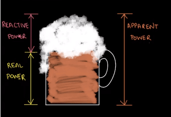
Beer Analogy:
A simple diagram can be illustrated to understand Power Factor considering the following analogy. The combination of drinkable beer(kW) and foam (kVAR) inside the mug represents the Apparent Power (kVA). That said, Power Factor is simply the ratio of Real Power (kW) to Apparent Power (kVA) and is represented by the following formula: PF = kW / kVA. Using our beer analogy, you can write the formula like this:
PF = Beer / Drinkable Beer + Foam
Power Triangle:
As Apparent Power is made up of two parts, the resistive power (the in-phase power in watts) and the reactive power (the out-of-phase power in volt-amperes), we can show the vector addition of these two power components in the form of a power triangle.
A power triangle has four parts: P, Q, S and θ.
The three elements which make up power in an AC circuit can be represented graphically by the three sides of a right-angled triangle as the previous impedance triangle. The horizontal (adjacent) side represents the circuits' real power (P), the vertical (opposite) side represents the circuits reactive power (Q) and the hypotenuse represents the resulting apparent power (S) of the power triangle as shown below.
Power Triangle of an AC Circuit:
- Where:
- P is the I2*R or Real Power that performs work measured in watts, W
- Q is the I2*X or Reactive Power measured in volt-amperes reactive, VAr
- S is the I2*Z or Apparent Power measured in volt-amperes, VA
- Φ is the phase angle in degrees. The larger the phase angle, the greater the reactive power
- Cos(Φ) = P/S = W/VA = power factor, p.f
- Sin(Φ) = Q/S = VAr/VA
- Tan(Φ) = Q/P = VAr/W
The power factor is calculated as the ratio of the Real Power to the Apparent Power as the ratio equals cos(Φ).
Low Power Factor is majorly caused by the huge inductive load which causes the reactive power to increase in magnitude, ultimately dropping the power factor. As discussed above, the lower power factor doesn't allow effective usage of electric power. From an industrial point of view, this low power factor results in the following causes.
Hello there! On a related topic, we previously wrote a blog about POWER FLOW ANALYSIS. If this peaks your interest, check it out and let us know what you think
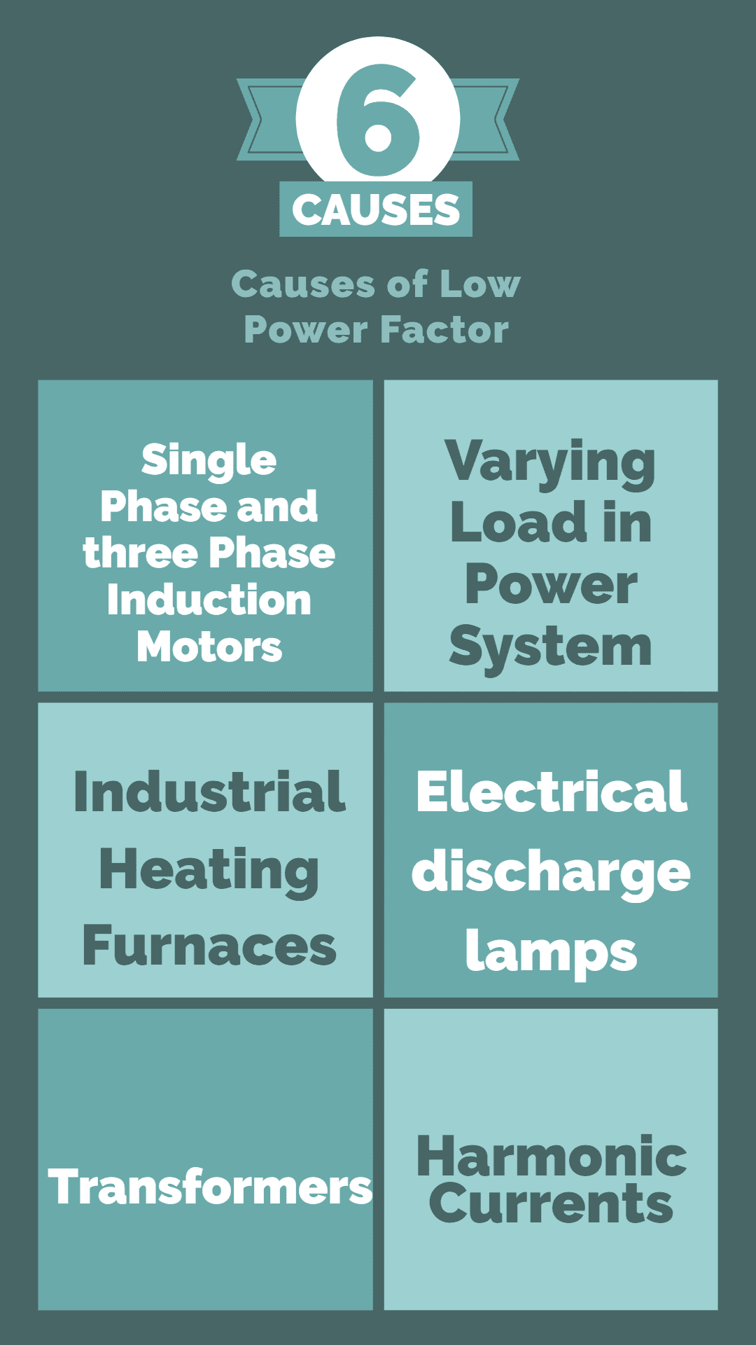
Causes of Low Power Factor:
The main cause of the low Power factor is Inductive Load. Current lags 90° from the voltage in a purely inductive circuit. This huge difference in phase angle between current and voltage causes zero power factor.
All circuits having capacitance or inductance have a power factor due to a difference of phase angle (θ) between current and voltage. An exception to this rule are resonance circuits (also called tuned circuits), where inductive reactance is equal to capacitive reactance (XL = Xc), so the circuit becomes a resistive circuit.
Following are the causes of low Power factor:
- Single phase and three phase induction motors. Usually, Induction motor works at poor power factor i.e. at:
Full load, Pf = 0.8 -0.9
Small load, Pf = 0.2 -0.3
No Load, Pf may drop to Zero (0)
2. Varying Load in Power System (when the power system is lightly loaded, the ratio of real power to reactive power is reduced, resulting in a decreased power factor).
3. Industrial heating furnaces.
4. Electrical discharge lamps (High-intensity discharge lighting) Arc lamps (which operate at a very low power factor).
5. Transformers.
6. Harmonic Currents.
Power Factor Unit:
Since power factor is the ratio of active power and apparent power, it has no unit. That said, it is the quantitative measure of how much effective power is being used, without a unit.
Power Factor Calculations:
It is imperative to know that power factor is only calculated for AC currents and circuits both for single phase and three phase. Following are some of the helpful formulae which can help in calculating the power factor of single and three phase circuit.
| Single Phase | Three Phase L-L | Three Phase L-N | |
| Main Calculation | PF = |cos φ| = 1000 × P(kW) / (V(V) × I(A)) | PF = |cos φ| = 1000 × P(kW) / (√3 × VL-L(V) × I(A)) | PF = |cos φ| = 1000 × P(kW) / (3 × VL-N(V) × I(A)) |
| Apparent Power | |S(kVA)| = V(V) × I(A) / 1000 | |S(kVA)| = √3 × VL-L(V) × I(A) / 1000 | |S(kVA)| = 3 × VL-N(V) × I(A) / 1000 |
| Real Power | Q(kVAR) = √(|S(kVA)|2 - P(kW)2) | Q(kVAR) = √(|S(kVA)|2 - P(kW)2) | Q(kVAR) = √(|S(kVA)|2 - P(kW)2) |
| Capacitor Capacitance | Scorrected (kVA) = P(kW) / PFcorrected Qcorrected (kVAR) = √(Scorrected (kVA)2 - P(kW)2) Qc (kVAR) = Q(kVAR) - Qcorrected (kVAR) C(F) = 1000 × Qc (kVAR) / (2πf(Hz)×V(V)2) |
Qc (kVAR) = Q(kVAR) - Qcorrected (kVAR) C(F) = 1000 × Qc (kVAR) / (2πf(Hz)×VL-L(V)2) |
Qc (kVAR) = Q(kVAR) - Qcorrected (kVAR) C(F) = 1000 × Qc (kVAR) / (3×2πf(Hz)×VL-N(V)2) |
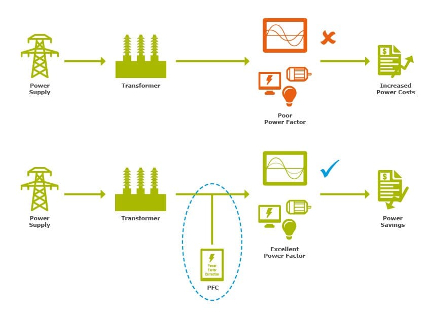
Power Factor Correction:
Power factor correction can be defined as the method of improving power factor value to make it reach unity or nearby unity value, such that the angle between voltage and current reduces. The following are the factors to be considered when carrying out power factor correction in three main conditions:
- When you design an AC source, such as generator, you need to make sure it will handle specified range of load power factors. Alternatively, you may need to specify a minimum allowable PF of the equipment powered from this source. For example, a capacitive load can make an electric generator unstable.
- When you design an AC-powered electronic power supply, you may have to meet the PF and harmonic limits of the applicable standards and/or specific requirements of the upstream source. This is usually accomplished by introducing active or passive power factor correction (PFC) circuit internal to the power supply.
- When you deal with electrical system in an industrial or commercial facility where the load properties are given, you may need to add external components (such as PFC capacitors) to raise the PF to an acceptable level to avoid surcharge or penalty fee.
Importance of Power Factor Correction:
Low Power Factor can be a problem for both consumers and generating utilities/stations, thus its improvement is vital for both:
For Consumers: The consumer pays the bill based on two factors; first, is his maximum demand in kVA and the units consumed. When the power factor is low, it causes maximum demand of power (kVA) to increase, resulting in an increased bill. That is why, Power Factor correction is performed, to reduce the total bill amount and annual saving.
For Generating Stations: The rating of generators is done in kVA but only kW is a useful output. As station output is kW = kVA x cos Φ,Power Factor determines the number of generated units. Power factor is desired to be as high as possible for a high kilo-watt hour rating, since it improves the cost and earing capacity of the station.
Meeting the increased KW demand in Power Stations:
The useful output of a power station is the kW output delivered by it to the supply system. Sometimes, a power station is required to deliver more kW to meet the increase in power demand. This can be achieved by either of the following two methods:
- By increasing the kVA capacity of the power station at the same power factor (say cos Φ1). Obviously, extra cost will be incurred to increase the kVA capacity of the station.
- By improving the power factor of the station from cos Φ1 to cos Φ2 without increasing the kVA capacity of the station. This will also involve extra cost on account of power factor correction equipment.
Knowing about power factor is very crucial for any electrical power system as it tells the amount of power wasted (Reactive Power) and consumed (Real Power) by it. Taking corrective measures will result in reduced power losses, increased voltage stability and eventually result in lowering the electric utility bills.


Abdur Rehman, PE
Author
Abdur Rehman is a professional electrical engineer with more than eight years of experience working with equipment from 208V to 115kV in both the Utility and Industrial & Commercial space. He has a particular focus on Power Systems Protection & Engineering Studies....
He earned his BSEE & MSEE from Washington State University in 2013 & 2017 respectively and an Engineering Technology Management degree in 2021.
Abdur Rehman is the CEO and co-founder of allumiax.com and creator of GeneralPAC by AllumiaX. He has been actively involved in various roles in the IEEE Seattle Section, IEEE PES Seattle, IEEE Region 6, and IEEE MGA.
Abdur Rehman is a board member of CordobaAcademy.org and enjoys local community volunteering. All AllumiaX blogs are special because of his love to share knowledge in the most intuitive way possible.
Stay Sharp & Join our Mailing List!
Subscribe to Allumiax Blog for updates on power system studies, tips, guides and insights on electrical engineering from industry leaders.

Recent Posts

Stay Sharp & Join our Mailing List!
Subscribe to Allumiax Blog for updates on power system studies, tips, guides and insights on electrical engineering from industry leaders.