Transformers — Its Working, Construction, Types, and Uses
They are an integral part of an electrical system and their application can be observed in almost all areas of electrical engineering ranging from the electrical power systems to common household appliances.
With the development of AC power sources, the need for transformers was also born. In the early times, DC power transmission was done resulting in greater losses and poor efficiency.
However, stepping up the transmission voltages using a transformer, this problem was solved. An increase in voltage is accompanied by a decrease in current to keep the power constant in a transformer.
And with power losses being directly proportional to the square of the current, results in a decrease in current by a factor of 10, consequently reducing losses by a factor of 100. Indeed, without transformers, we would not have been able to use electric power as we use it now.
That is why we generate electricity at voltages of up to 11 to 25 kV and then step up them to 132,220 or 500 kV for transmission with minimum losses and then we later step down the voltage for safe residential and commercial use.
Construction of a transformer
A transformer consists mainly of a core, windings and a tank, however, bushings, breathers, radiators, and conservators are also present in some transformers.
Core: A transformer core is made of soft iron or silicon steel which provides a low reluctance path (magnetic field lines can easily pass through them).
Transformer cores are laminated to reduce eddy current losses, the laminations are usually 2.5 mm to 5 mm thick and are insulated from each other and the windings by a coating of oxide, phosphate or varnish. The Core is constructed with the laminations in different shapes such as E, L, I, C and U.

In shell-type transformers, the core surrounds or covers the windings like a shell.
In core-type transformers, the windings are wrapped around the two limbs or rectangles of the core.
Windings:
A single-phase 2 winding transformer has generally 2 windings, primary and secondary windings which are made from high quality stranded copper. The windings are coiled around the core and have completely no electrical contact with each other.
They can also be called High voltage and Low voltage windings respectively, with the high voltage winding having greater insulation than the low voltage winding.
Working principle:
The basic operating principle of a transformer is the work of mutual induction between the primary and secondary windings which are linked by a common magnetic flux through the transformer core. The core provides a path of low reluctance for the magnetic flux to pass through.
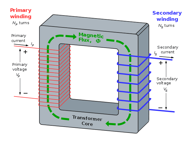
By BillC at the English language Wikipedia, CC BY-SA 3.0, Link
A transformer has a primary winding and secondary winding as discussed above. The winding connected to the source can be considered as a primary winding and the current it is carrying can be considered to have a magnetic field of its own.
This magnetic field is created across the core and is changing directions due to alternating currents, and now according to Faraday's law of electromagnetic induction:
The Rate of change of flux linkage with respect to time is directly proportional to the EMF induced in a conductor or coil
This change in the magnetic field induces a voltage on the secondary coil which is proportional to the number of turns on the windings. This can be further understood by the following equation:
Where :
E = induced EMF
N = the number of turns
dΦ = change in flux
dt = change in time
Transformer turns ratio:
Both the windings on a transformer I.e. primary and secondary have a specific number of turns. The ratio of the number of turns on the primary winding to the number of turns on the secondary winding is known as the turns ratio.
Where :
NP = Primary winding turns
NS = Secondary winding turns
Ideal Transformer:
An ideal transformer is a transformer which gives a power output that is exactly equal to the power input. This means that it does not have any type of loss.
Ideal transformers do not exist and are only used to simplify transformer calculations. Their voltage ratio can be modeled by these simple equations:
Where :
VP = Primary side voltage
VS = Secondary side voltage
And power is given by:
Pin = Pout
And
Pin = VP IP cosθP
Pout = VS IS cosθS
Or
VP IP = VS IS
Where :
Pin = input power
Pout = output power
cosθ = input power factor
In other words, an ideal transformer will have 100% efficiency due to no power losses.
We can suppose that an ideal transformer will have zero winding resistance, no leakage flux, and no copper or core losses.
Equivalent circuit of an ideal transformer:

The equivalent circuit of an ideal transformer will not model any resistance nor any reactance because all types of losses present are considered to be non-existent. So, what we get is a very simplified circuit diagram.
How an Ideal Transformer is different from a Real Transformer?
In actuality, we have transformers that consist of some power losses; hence the output power is never equal to the input power of the transformer.
Real transformers will have some value of winding resistance, will have leakage flux and will also be having copper and core losses which we will be discussing below.
Magnetization current:

This is the current required to produce flux in a transformer core (or magnetize it).
It can be observed that when a transformer is given an AC supply while making an open circuit at the secondary, a small current will still flow through the primary side.
This current consists of the magnetization current(im) and core-loss current(ih+e).
Some important points about magnetization current are that:
- It is not pure sinusoidal and will have higher frequency components once the core starts to saturate.
- Once the core reaches its maximum flux, then a small increase influx will require a very high magnetization current.
The sum of magnetization current and core loss current is then known as transformer excitation current.
iex = im + ih+e
Losses:
A transformer is a static device and does not has any rotating part, so it has no rotational losses. However, it does have the following electrical losses:
- Core or Iron losses
- Copper losses
Core Losses:
Core losses are called iron losses because they are related or are a consequence of the iron transformer core.
They can be broken down into 2 parts.
- Hysteresis Loss
- Eddy Current Losses
Hysteresis Loss:
Any ferromagnetic material can be considered to have many small magnetic domains (small permanent magnets) that point in random directions. When an external magnetic field is applied to the iron, these domains align themselves in the direction of the field.
However, as the AC current changes its direction, the magnetic field also changes its direction and the magnetic domains must also change their directions in accordance with the magnetic field.
Some magnetics domains will align but some will require further energy to align them. This energy required for the re-orientation of the magnetic domains during each cycle of an alternating current is known as Hysteresis Loss.
Eddy Current Losses:
The alternating flux in the transformer core links with the secondary windings and induces a voltage on it according to faraday's law.
It is also likely that this alternating flux will link with other conducting parts of the transformer such as the iron core and iron casing or body.
This alternating flux will then induce localized voltages in these parts, which will then result in swirls of current to flow within them. These currents are known as Eddy currents.
These currents cause energy losses due to the resistivity of the core or conducting part on which they originate hence energy is dissipated as heat.
Both hysteresis and eddy current losses result in the heating of the transformer core.
Copper Losses:
The primary and secondary windings of the transformer will always have some value of resistance of their own and a flow of current through this resistance will always result in energy losses.
Because the windings are made of copper, the energy or heat losses in them are known as copper losses.
Copper losses can be given by:
Pcu = I2R
So, the greater the magnitude of the current, the greater will be the copper losses. That is why these losses are also known as variable losses as they are load-dependent.
Leakage Reactance:
The primary and secondary windings produce their own flux, which is linked together with each other, this is known as mutual flux.
However, not all the magnetic flux between the primary and secondary winding is linked.
Some flux produced by the primary winding will not link with the secondary winding, while some amount of flux produced by the secondary winding will not link with the primary winding.
This flux which links with only one of the windings instead of linking with both is known as leakage flux.
The windings being inductive in nature, this leakage flux will produce a self-reactance or impedance in the windings which are known as leakage reactance.
This leakage reactance will cause voltage drops in the primary and secondary windings.
Transformer Equivalent Circuit:
An equivalent circuit of a transformer is a simplified representation of a transformer comprising of the resistances and reactances.
An equivalent circuit helps us in performing transformer calculations as basic circuit analysis can now be applied to a transformer.

Resistor RP and Resistor RS:
These resistors model the resistive copper losses in a transformer and are easily represented.
XM:
As we have mentioned earlier that the excitation or no-load current is equal to the sum of magnetization and core loss current.
So, the magnetization current can be modeled by the reactance XM connected across the primary voltage source.
RC:
The core losses consisting of eddy current losses and hysteresis losses can be modeled by resistance RC connected across the primary voltage source
Xm and Rc are known as the excitation branch.
XP and XS:
Xp is the leakage reactance at the primary winding while XS is the leakage reactance at the secondary winding.
Referring to primary and secondary sides:
The equivalent circuit shown above is an accurate representation of a transformer. However, to solve practical transformer circuits, it is necessary to convert the entire circuit to a single voltage level.
This is done by referring the circuit to its primary or secondary side.
To the primary side:
To refer or convert the circuit to the primary side we first find the value of a constant ''a''.
Now that we have found 'a', we can convert the secondary sides resistance Rs and reactance Xs to the primary side by multiplying them both by a2.
RS' = RS x a2
XS' = XS x a2
The secondary voltages Vs is multiplied by 'a', while the secondary current Is is divided by 'a'.
V 'S = VS x a
And
To the secondary side:
Given the value of constant 'a', we divide the values of primary side resistance and reactance by a2.
The same will be done for XM and RC.
And
The primary current will be multiplied by 'a', while the primary voltage will be divided by 'a'.
I 'S = IS x a
And
Once we have referred our values to one particular side, either primary or secondary, we can then move the excitation branch to the front and add the Resistances and Reactances in series together as shown in the circuit diagrams.
Efficiency:
Transformer efficiency is the ratio of transformer output power to the input power.
It is given by
Or
Where :
Pin = input power
Pout = output power
PLOSS = power losses
As the output power will always be less than the input power, transformer efficiency will always lie between 0-100% while an ideal transformer will have an efficiency of 100%.
To calculate the transformer efficiency from an equivalent circuit we just add the copper losses and core losses to the efficiency equation to get the following equation:
Voltage Regulation:
It is also important to know that because a transformer has series impedances within it, it will have voltage drops across them as well. This will result in varying output voltage with the varying load even if the input voltage is kept constant.
The quantity that compares the output voltage at no load to the output voltage at full load is known as voltage regulation.
It can be calculated from the following equation:
Where :
VS.NL = Output voltage at No Load
VS.FL = Output voltage at Full Load
It should be noted that an ideal transformer will have a voltage regulation of 0%.
Transformer types and their applications
Hello there! On a related topic, we previously wrote a blog about Types of Transformer. If this peaks your interest, check it out and let us know what you think
Step-Up Transformer:
These transformers increase the lower voltage level on the primary side to a higher voltage value on the secondary side. In this case, the secondary winding has a greater number of turns than the primary one.
These are mainly used in generating stations where the generated voltage of about 11 kV is stepped up to 132 kV or more for transmission.

Step-Down Transformer:
Step down transformers reduces the high voltage at the primary side to a lower voltage value on the secondary side. In this case, the primary winding has a greater number of turns.
Step down transformers are used at grid stations to decrease the high transmission voltages to a suitable lower value for distribution and utilization. They can also be found on our mobile chargers.

Other types include Power transformers, Distribution transformers, Core type transformers, Single and three phase transformers, Indoor and outdoor transformers. You may check our previous blog focusing on transformer types and their applications.
Limitations of a transformer:
It is also important to note here that a transformer will only operate in AC. This is because a Direct Current (DC) will produce a constant magnetic field instead of a changing magnetic field and hence no emf will be induced in the secondary winding.
This concludes our topic of transformers. We hope that this blog was helpful and gave you valuable information on the topic. Feel free to suggest or ask any questions you might have in the comments section below. Thank you.


Abdur Rehman, PE
Author
Abdur Rehman is a professional electrical engineer with more than eight years of experience working with equipment from 208V to 115kV in both the Utility and Industrial & Commercial space. He has a particular focus on Power Systems Protection & Engineering Studies....
He earned his BSEE & MSEE from Washington State University in 2013 & 2017 respectively and an Engineering Technology Management degree in 2021.
Abdur Rehman is the CEO and co-founder of allumiax.com and creator of GeneralPAC by AllumiaX. He has been actively involved in various roles in the IEEE Seattle Section, IEEE PES Seattle, IEEE Region 6, and IEEE MGA.
Abdur Rehman is a board member of CordobaAcademy.org and enjoys local community volunteering. All AllumiaX blogs are special because of his love to share knowledge in the most intuitive way possible.
Stay Sharp & Join our Mailing List!
Subscribe to Allumiax Blog for updates on power system studies, tips, guides and insights on electrical engineering from industry leaders.

Recent Posts

Stay Sharp & Join our Mailing List!
Subscribe to Allumiax Blog for updates on power system studies, tips, guides and insights on electrical engineering from industry leaders.