Induction Motors and Their Impact on Power Systems
The power system is a network of complex, interconnected components, important for ensuring a reliable electricity supply and distribution. At the heart of this system, induction motors play a crucial role, driving critical machinery such as compressors, pumps, and conveyor belts in industrial and power plant settings. Their extensive use has a significant impact on the power system, which requires careful management and analysis to prevent potential issues.
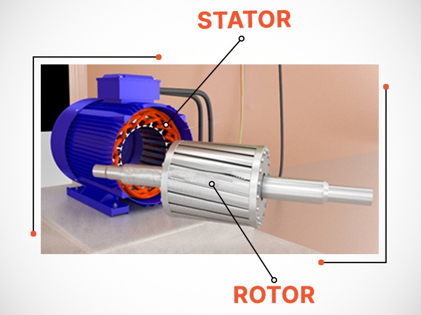
So, the important question is how do induction motors work? Well, they operate on the principle of electromagnetic induction. In simple terms, an electric current is induced in the rotor by the magnetic field in the stator. These motors consist of two main parts:
- Stator: The stationary part that generates a rotating magnetic field when an alternating current (AC) is applied.
- Rotor: The rotating part housed inside the stator, which can either be a squirrel cage or a wound type.
Moreover, induction motors play a crucial role in power system studies, including short-circuit analysis, protection coordination, and arc flash analysis. These studies are critical for ensuring the reliability and safety of power systems.
In this blog, we will explore the important parameters of induction motors and their significant contributions to these essential power system studies.
Motors Parameters Affecting Power System Studies:
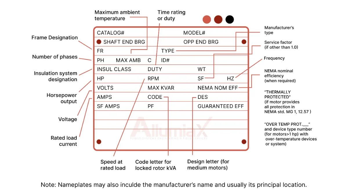
The motor nameplate, shown below, contains essential specifications that are crucial for power system studies. Key parameters of induction motors, as outlined in this blog, are derived directly from the nameplate data. These parameters play a vital role in ensuring accurate power system analysis, impacting overall system performance and efficiency.
Rated Voltage
Rated Voltage is the voltage level at which a motor is designed to operate optimally, as specified by the manufacturer. It ensures that the motor functions at its full capacity without excessive heat or damage. Operating a motor at its rated voltage allows it to deliver the required performance and efficiency. Deviation from the rated voltage can lead to overheating, reduced efficiency, or even motor failure.
Full-Load Current (FLA)
Full-Load Current (FLA) is the current motor draws when operating at its rated load and rated voltage. Rated load refers to the maximum load the motor is designed to manage safely, while the rated voltage is the voltage the motor is designed to run on.
Inrush current
Inrush current is the maximum current a motor draws when it starts. It is much higher than the normal operating current, typically 5 to 10 times greater, and lasts for a few seconds before dropping down to the normal operating current.
Locked Rotor Current is similar in magnitude to inrush current but occurs when the rotor is unable to rotate due to a mechanical issue or heavy load.
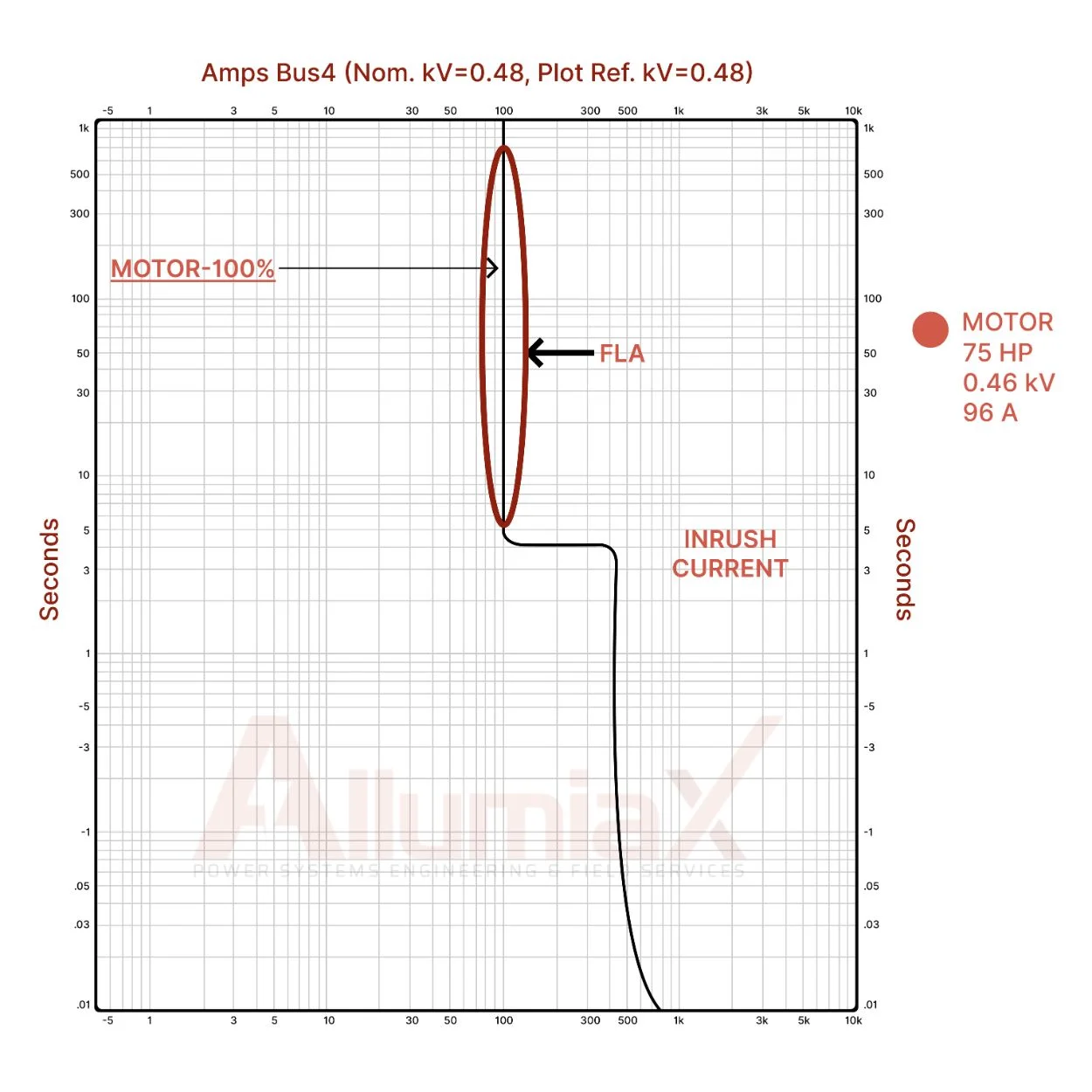
Below is the time-current curve for the 75 HP motor, which shows the Full Load Amperage (FLA) as 96 amps and the inrush current as 576 amps during motor startup. When setting the breaker, it is crucial to ensure that the breaker’s protection settings are adjusted to the right of this curve. This will properly protect the motor from overloads and short circuits, while allowing the normal inrush current during startup.
Starting Torque
The torque developed by an induction motor when it starts from rest to overcome the inertia of the load. This is important in power systems because it leads to high inrush current and has serious impact on power system which we will discuss later in the blog
Impedance of Induction Motors
Impedance is the total opposition to the flow of current in an AC circuit and is the sum of resistance (R) and reactance (X). In power systems, especially when dealing with motors, understanding impedance is crucial because motors can generate significant fault currents and, in some cases, act like generators during faults, backfeeding the system.
A motor with high impedance will limit the flow of fault current, as the higher the impedance, the greater the opposition to current flow. On the other hand, a motor with low impedance will allow more current to flow, creating higher fault currents.
Service Factor
The service factor (SF) of an induction motor indicates its ability to handle temporary overloads. A value of 1.0 means continuous operation at full load, while 1.15 allows for brief operation at 115% of the rated load.
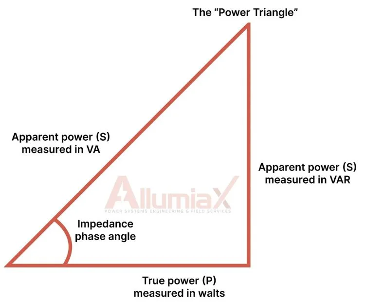
Power Factor
Power factor is the ratio of real power (P) to apparent power (S) in a system. An induction motor is inductive in nature, meaning it has a lagging power factor, where the current lags the voltage. A low power factor indicates that the motor is drawing more reactive power (instead of real power) to maintain its operation. This means that, for the same amount of real power being used to perform the motor's task, more current is drawn from the system.
The impact on the power system and related studies will be discussed later in this blog.
Motor Starting Mechanisms: DOL, VFD, and Star-Delta
When motors start, they draw a large inrush current that can potentially damage equipment or cause nuisance tripping. Several starting methods are used to control this inrush current:
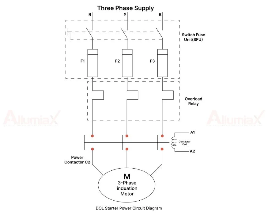
- Direct-On-Line (DOL): This method involves directly connecting the motor to the power supply, resulting in a significant inrush current at startup. While DOL is a straightforward and cost-effective approach, it can cause substantial voltage dips and lead to increased strain on the system due to the high current draw.
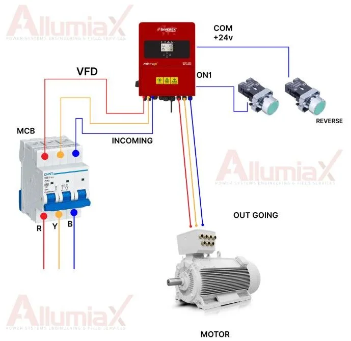
- Variable Frequency Drive (VFD): VFDs control the motor’s speed by adjusting the frequency of the power supplied, which results in a smoother startup and limits the inrush current. VFDs also prevent motor from back feeding current into the system.
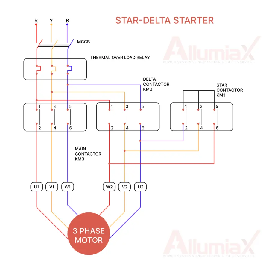
- Star-Delta: In this method, the motor starts in a star (Y) configuration, which reduces the starting current. Once the motor reaches a certain speed, it switches to a delta (Δ) configuration for full voltage operation.
Understanding these parameters is essential not only for assessing the motor’s performance but also for predicting their influence on key power system studies, such as motor starting, arc flash analysis, protection coordination, and short-circuit analysis.
We previously published a blog on the Importance of Motor Starting Studies in Power System. Checked it out to grasp the information available in this blog.
In the following sections, we will examine how these parameters impact each of these critical aspects of power system studies, followed by a conclusion.
Motors Impact on Arc flash analysis
Arc flash is a hazardous event where an electrical discharge travels through the air, causing severe heat, light, and pressure, leading to serious injuries and equipment damage. Arc flash analysis aims to determine the incident energy at fault points to design effective safety measures and Personal Protective Equipment (PPE). The NFPA (National Fire Protection Association) mandates that companies perform arc flash hazard analyses as part of their compliance with NFPA 70E standards. This analysis must be conducted at least every five years to identify potential hazards and ensure the safety of personnel.
Induction motors play a significant role in arc flash incidents. When these motors start, they draw a high inrush current, often 5 to 10 times greater than their normal operating current, which spikes incident energy and increases the risk of arc flash. Locked rotor current, occurring when the motor's rotor is stationary, also results in high sustained currents that elevate incident energy and potential hazards. The impedance of motor components, combining resistance and reactance, impacts fault currents. High impedance helps limit fault currents and reduce arc flash severity, while low impedance allows higher currents, increasing the risk.
By understanding these key parameters and applying mitigation strategies, engineers can develop protective measures, accurately coordinate devices, and minimize risks, ensuring safety and reliability in power systems. Compliance with NFPA 70E standards through regular arc flash analysis is essential to maintain a safe working environment and protect personnel from the dangers of arc flash incidents.
Impact On Protective Device Coordination Study
Protective coordination ensures the safe and reliable operation of electrical systems by managing how protective devices like circuit breakers and relays function to isolate faults effectively. The goal is to ensure that the devices that are closest to the fault, trips first. The NEC (National Electrical Code) standards emphasize the importance of proper protective coordination for system safety and reliability.
During motor startup, inrush current can be high enough to trigger a protection system if the settings are too sensitive. Protective coordination studies must account for these high inrush currents to avoid nuisance tripping. Proper coordination ensures that the motor operates without interruption during normal startup while still being protected during fault conditions.
Additionally, parameters like power factors play a crucial role in coordination studies. Motor operating at a low power factor may cause voltage drops that could affect other protective devices, requiring engineers to adjust protection settings accordingly. This adjustment helps ensure that the power system operates safely and efficiently, minimizing unnecessary downtime.
By understanding and managing key factors like inrush current, starting torque, impedance, and power factor, it is possible to ensure effective protection coordination in the system. This improves overall reliability, reduces unnecessary interruptions, and helps maintain a safe and stable electrical infrastructure. Adhering to industry standards, such as those outlined by the NEC, is crucial to keeping these protections in place.
Parameters Affecting Short Circuit Studies
Short-circuit studies are crucial for understanding how a power system responds to faults, and induction motors significantly impact these studies by contributing to fault currents. Key parameters include impedance, full-load current, locked rotor current, power factor, and motor start-up characteristics.
Motors with low impedance can lead to higher fault currents, potentially overwhelming protection devices. This can cause equipment damage and system instability, as protection devices may trip too late or fail to isolate the fault. Conversely, high impedance motors help limit fault currents, reducing the severity of fault conditions. However, this can delay fault detection because lower current levels might not trigger the protective devices promptly, risking prolonged fault conditions.
Full-load current and locked rotor current are critical in determining the magnitude of the fault current. High full-load and locked rotor currents can exacerbate fault conditions, making protective devices respond more aggressively, which is necessary to prevent damage. Accurate settings for these currents ensure devices operate correctly during different motor states.
Beyond these key parameters, it is also important to consider how motors contribute to fault currents, especially in the context of motor backfeeding during fault conditions.
Motor Short Circuit Contribution
Motor contribution to fault current is a critical aspect of power system studies, particularly when considering motor backfeeding during fault conditions.
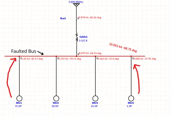
Under normal operation, an induction motor’s rotor runs at a speed slightly slower than the synchronous speed of the stator’s rotating magnetic field, a phenomenon known as slip. However, during a fault, the rotor’s inertia allows it to continue spinning even after the stator’s magnetic field is disrupted. If the rotor’s speed surpasses synchronous speed, it behaves like a generator, backfeeding power into the system and contributing to the fault current.
The effect of motor backfeeding becomes more pronounced with larger motors. As motor horsepower (hp) increases, the amount of fault backfeed also increases, which can influence system behavior and protective coordination.
The following image illustrates this relationship, showing how different motor sizes contribute to fault current.
Motor Starting Study
A Motor Starting Study is an analysis to assess how a motor’s startup impacts the electrical system, focusing on the high inrush current drawn when the motor starts. This inrush current can cause voltage dips or fluctuations, potentially affecting other equipment and triggering unnecessary trips of protection devices. The primary goal of this study is to ensure that the system can manage the transient effects of motor startup, such as maintaining voltage stability and preventing system instability. It also ensures that protective devices, like circuit breakers, do not trip unnecessarily due to the inrush current and that the system remains stable even if multiple motors start simultaneously. Motor starting studies are especially important for large or critical motors, as improper management can lead to equipment damage or operational downtime. For a more detailed explanation, refer to our in-depth blog on motor starting studies.
Utilizing Induction Motors to Enhance Power System Performance
Induction motors are indispensable in power systems, but their parameters—such as inrush current, locked rotor current, and power factor can cause significant disruptions if not properly managed. These factors directly impact critical system studies like short-circuit analysis, arc flash risks, and protection coordination, potentially leading to safety hazards, operational downtime, and costly inefficiencies.
By understanding and optimizing motor parameters, engineers can mitigate these risks, ensuring smoother startups, preventing nuisance trips, and maintaining system stability. Accurate modeling of motor behavior helps improve coordination between protective devices, reducing fault currents and enhancing overall system reliability.
For facility owners and engineers, this knowledge is crucial. The impact of poor motor management is real—whether it's unexpected equipment failure, safety incidents, or costly operational delays. Taking the time to understand and optimize motor parameters now can save time, money, and most importantly, ensure a safer, more reliable power system for the long term
Our team of expert engineers are equipped to oversee these complexities, offering tailored solutions through detailed motor starting study, short-circuit studies, arc flash analysis, and effective protective coordination. Let us manage the intricate details, ensuring your power infrastructure remains robust and reliable. Get in touch with us or Request a Quote.


Abdur Rehman, PE
Author
Abdur Rehman is a professional electrical engineer with more than eight years of experience working with equipment from 208V to 115kV in both the Utility and Industrial & Commercial space. He has a particular focus on Power Systems Protection & Engineering Studies....
He earned his BSEE & MSEE from Washington State University in 2013 & 2017 respectively and an Engineering Technology Management degree in 2021.
Abdur Rehman is the CEO and co-founder of allumiax.com and creator of GeneralPAC by AllumiaX. He has been actively involved in various roles in the IEEE Seattle Section, IEEE PES Seattle, IEEE Region 6, and IEEE MGA.
Abdur Rehman is a board member of CordobaAcademy.org and enjoys local community volunteering. All AllumiaX blogs are special because of his love to share knowledge in the most intuitive way possible.
Stay Sharp & Join our Mailing List!
Subscribe to Allumiax Blog for updates on power system studies, tips, guides and insights on electrical engineering from industry leaders.

Recent Posts

Stay Sharp & Join our Mailing List!
Subscribe to Allumiax Blog for updates on power system studies, tips, guides and insights on electrical engineering from industry leaders.