Minimizing Arc Flash Hazard Using Maintenance Mode

An arc flash hazard is a dangerous electrical event that occurs when an unintended luminous bridge or arc is formed between conductors. The incident energy released during arc flash incidents can result in severe injuries, burns, and even fatalities to individuals working on or near electrical equipment. Therefore, mitigation of arc flash incident energy is the most crucial part of an arc flash hazard study.
There are several techniques and methods that can be used to reduce the high incident energies identified by arc flash hazard study and calculation. One of the most economical and efficient techniques is to use arc flash reduction maintenance system which is simply a specialized feature or setting in the primary protective device, most commonly in the line side main breaker.
How to Reduce Arc Flash Exposure?
Mitigating arc flash hazards requires a combination of engineering controls, administrative controls, proper training, and the use of appropriate personal protective equipment . Here are the solutions that can be applied to reduce arc-flash hazards.
- Arc Flash Training of personnel
- Adopt good safety practices to minimize hazard
- Reduce available fault currents
- Reduce fault clearing time
- Increase working distance
- Use Personal Protective Equipment (PPE)
Among all the above stated solutions the most practical and effective way is to reduce fault clearing time. Let’s discuss the working of an arc flash reduction maintenance system in circuit breakers which is being used in industries to make the system more responsive to faulty conditions by achieving fast tripping of protective device.
About Arc Flash Reduction Maintenance System
The arc flash reduction maintenance system consists of a circuit breaker with an additional integral switch. It has two independent functions designed for operation under normal and faulty scenarios.
- Normal Mode:
When the system is in normal operation the circuit breaker trip unit settings are set with intentional delays as per selective coordination requirement.
We recently published a blog on the Selective Coordination Requirements NEC 700,701 and 702 Systems. Checked it out to grasp the information available in this blog.
- Maintenance Mode:
This mode is activated when the personnel must work on energized equipment for performing maintenance or any required task. In this function the protective device will override the existing delay functions and trip the circuit instantaneously. Proper equipment maintenance planning is essential to ensure safety and reliability in such cases.
The purpose of this feature is to reduce arc flash energy at downstream feeder circuit breakers. By installing maintenance switch at line side, the incident energy at load side is significantly reduced.
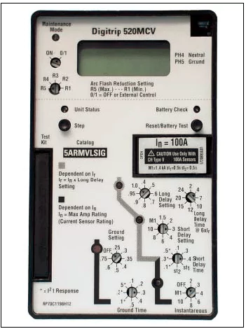
Figure (1) Circuit breaker with Arc Flash Reduction System
When do we need a circuit breaker with arc flash reduction maintenance system?
The fact that makes a system well-tuned without maintenance switch is the magnitude of arcing fault current present in the system which lies under the short or instantaneous region of respective protective devices.
In contrast, if there is a system in which protective devices are not able to clear the arcing fault current instantaneously. In such cases, there is an increased risk of arc flash exposure to the personnel working at load side for maintenance purpose. Now, the need of such maintenance mode in circuit breaker arises in the system, which is meant to override the coordination of protective devices and consequently reduce the arc flash energies at the load side.
It is very important to note that the maintenance mode of circuit breaker is turned on only during an event of maintenance considering the safety of personnel. In normal condition, the protective devices would maintain the coordination among them as now the personnel are out of danger.
Setting an arc flash reduction maintenance system in circuit breakers
By performing the arc flash study on the system, the incident energy (calories/cm2) and fault clearing time can be found. Now, consider the cases in which fault clearing time is longer than 2 seconds. As arc duration of 2 seconds is assumed to determine the incident energy according to IEEE Standard 1584-2018. After short listing such cases, the lowest arcing fault current needs to be considered for setting your maintenance mode switch. Make sure that the lowest arcing fault found in your system comes under the instantaneous region of circuit breaker in maintenance mode.
Modelling arc flash reduction maintenance system of circuit breaker using ETAP
System Overview:
The system consist of utility supply, which provides a fault current of 20kA. Protecting the downstream panels, we have our primary line of defense: the Main Circuit Breaker(Main CB), with an interrupting rating of 65kA. The Main Circuit Breaker feeds the panels named as Panel A and Panel B with their respective connected circuit breakers FDR PNL A and FDR PNL B. Considering, these panels house critical loads that need to be safeguarded during both routine operations and maintenance activities.
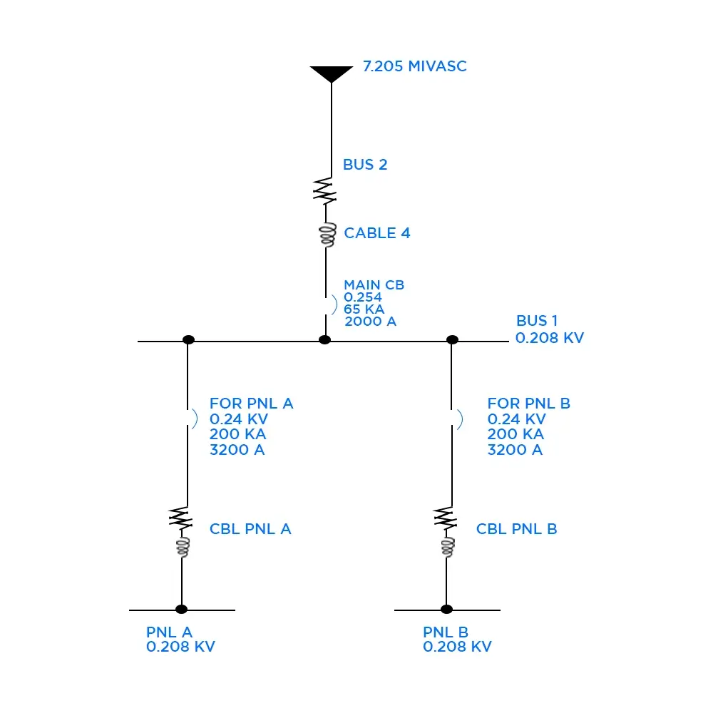
Figure (2) System Modeled on ETAP
- Utility, Fault current 20KA.
- Cuttler Hammer, Circuit Breaker (Main CB).
- Cuttler Hammer, Circuit Breaker (FDR PNL A and FDR PNL B).
Maintenance mode settings
- Not all circuit breakers are equipped with maintenance mode settings. It's important to recognize that the availability of maintenance mode is often specific to certain models and provided by the Original Equipment Manufacturer (OEM).
- circuit breakers with maintenance mode settings tend to be more expensive than their counterparts without this feature. This cost difference is attributed to the additional technology and engineering required to implement and ensure the reliability of maintenance mode functionalities.
Here is how you can select the circuit breaker in our model that you'd like to have the maintenance mode feature for, and then follow these steps.

Figure (3a) Selection of Maintenance Mode Breaker on ETAP
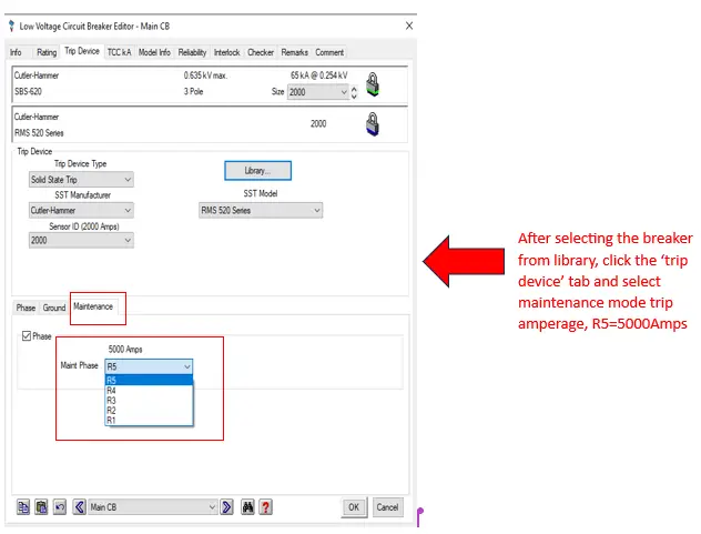
Figure (3b) Selection of Maintenance Mode Breaker with minimum trip amperage on ETAP
Scenario:
Normal Utility Scenario (Maintenance Switch is Off):
In our SLD, the initial scenario shows utility operations, under regular conditions. However, this standard operation shows relatively high incident energy levels and longer fault clearing times, which can be dangerous for personnel conducting maintenance or repairs.
As We can see that when we run ARC FLASH in this senario here at PNL A and PNL B both have Incident Energy as “34 cal/cm2” and our Fault clearing time (FCT) is “ 2 sec”. ”
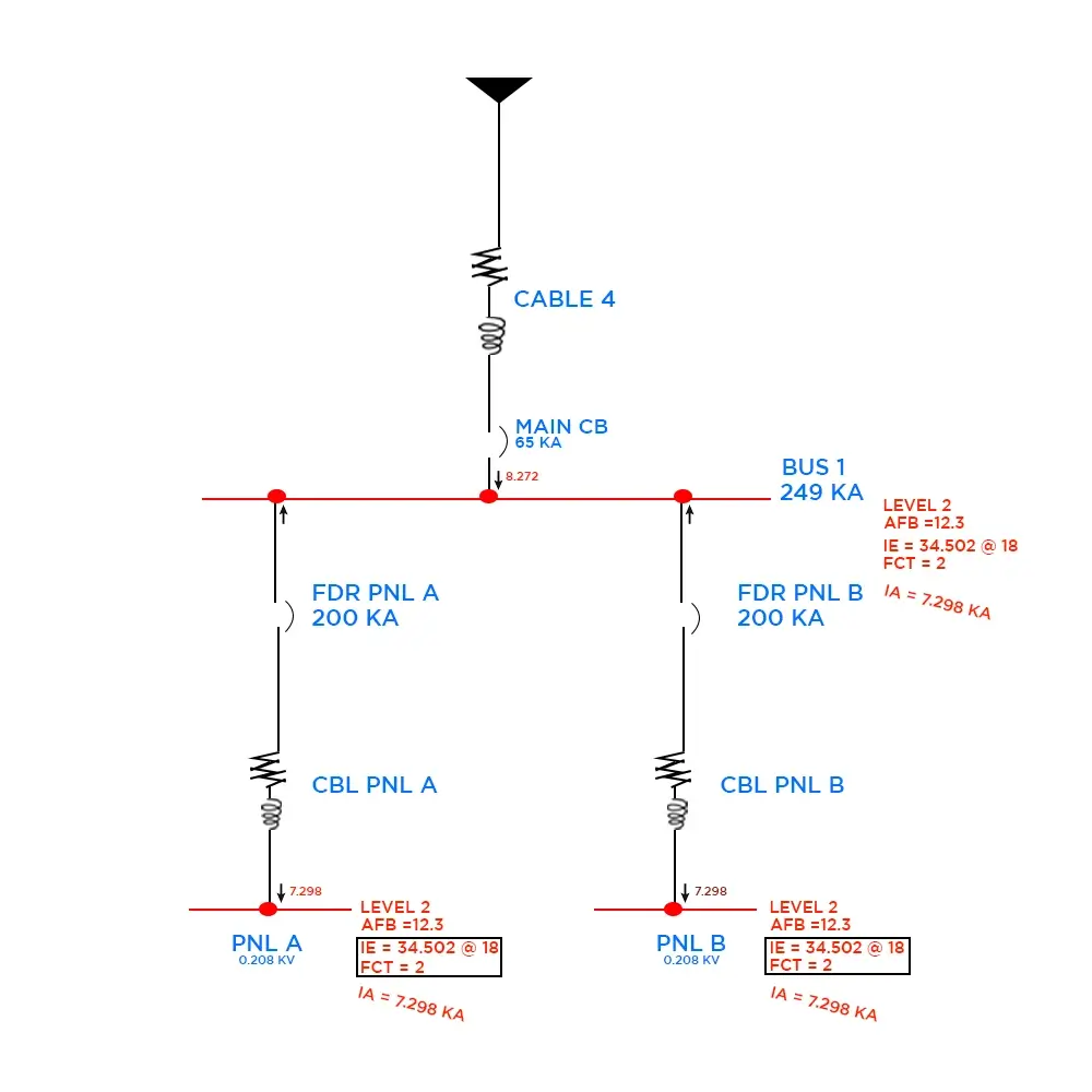
Figure (4) ARC FLASH without activation of maintenance mode
Maintenance Mode Scenario (Maintenance Switch is On):
By adding maintenance mode switches, we can enhance safety. When these switches are activated, they effectively isolate Panel A and Panel B from the main circuit, reducing incident energy and shortening fault-clearing times.
In this mode, the breaker prioritizes rapid fault clearance with an instantaneous response, bypassing certain time delays present in its normal operation. This adjustment significantly reduces the duration of arcing events, ensuring fast interruption of fault currents. Consequently, the shorter arcing duration results in lower incident energy. By minimizing downtime and mitigating potential hazards, the maintenance mode Main CB creates a safer working environment for personnel involved in electrical system maintenance or repair.
As we can see that when we run ARC FLASH in this senario here at PNL A and PNL B both have Incident Energy as “0.863 cal/cm2” and our Fault clearing time (FCT) is “0.05 sec”.
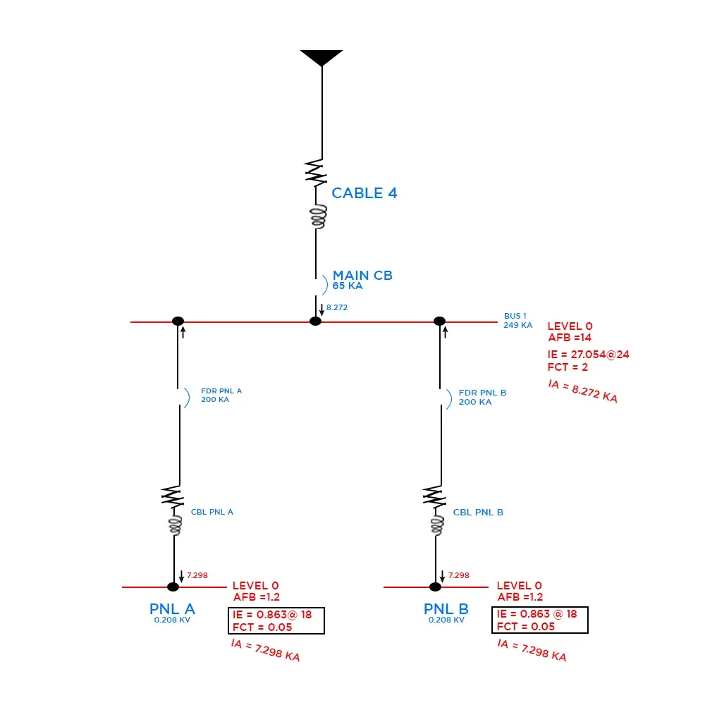
Figure (5) ARC FLASH after maintenance mode activation
WITHOUT MAINTENANCE MODE ACTIVATION:
| ID | kV (kV) | Type | Total Energy (cal/cm²) | AFB (ft-in) | Energy Levels | Final FCT (sec) | Source PD ID | Ia at FCT (kA) |
|---|---|---|---|---|---|---|---|---|
| PNL A | 0.208 | Panelboard | 34.5 | 12'3" | Level 2 | 2 | FDR PNL A | 7.298 |
| PNL B | 0.208 | Panelboard | 34.5 | 12'3" | Level 2 | 2 | FDR PNL B |
7.298 |
AFTER MAINTENANCE MODE ACTIVATION:
| ID | kV (kV) | Type | Total Energy (cal/cm²) | AFB (ft-in) | Energy Levels | Final FCT (sec) | Source PD ID | Ia at FCT (kA) |
|---|---|---|---|---|---|---|---|---|
| PNL A | 0.208 | Panelboard | 0.86 | 1'3" | Level 0 | 0.05 | Main CB | 7.298 |
| PNL B | 0.208 | Panelboard | 0.86 | 1'3" | Level 0 | 0.05 | Main CB |
7.298 |
Maintenance mode illustration using TCC
NORMAL MODE:
The diagram illustrates the Time Current Characteristics (TCC) of two breakers: Main CB and FDR Panel A. We have introduced a fault current of approximately 20KA from the utility, which is reduced to 7.2KA due to the resistance of the cables within the system.
We recently published a blog on the Time Current Characteristic Curves for Selective Coordination. Checked it out to grasp the information available in this blog.
It's noteworthy that when the maintenance mode of Main CB is not enabled, the breaker becomes active as the fault current of 7.2KA enters its short-time region, resulting in fault current isolation in 2 seconds.
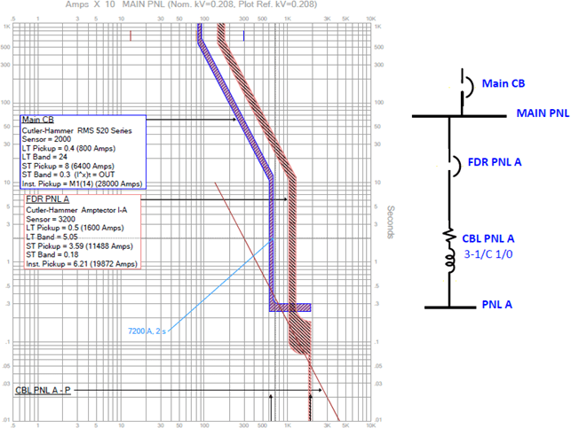
Figure (6) Coordination of breakers without activating maintenance mode
MAINTENANCE MODE:
In the second scenario, the fault current from the utility to Panel A measures 7.2 kiloamperes (KA). Our primary circuit breaker, Main CB, serves as the main protective device for the Main Panel (Main PNL) and has maintenance mode settings.
Here, we have activated the maintenance mode feature of the Main CB with phase setting at R5 (5000A) and assess that whenever a fault current greater than or equal to 5000A is detected by this circuit breaker, it will instantaneously isolate the fault current.
We observe that the isolation achieved by the maintenance mode of Main CB is 1.5 times faster than its standard isolation response. The Time Current Characteristic (TCC) of the maintenance mode appears ahead of its normal TCC because it is configured for 5000A, while our fault current is 7.2KA. When the fault current surpasses 4.9KA then breaker will trip within 0.05 seconds.
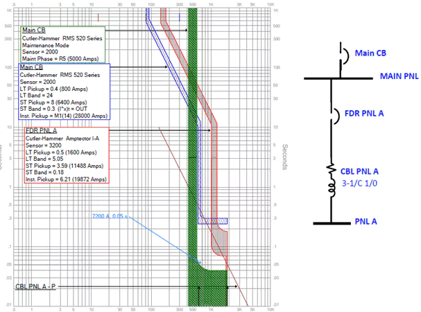
Figure (7) Swift response of the maintenance mode breaker in isolating the fault
Benefits Of Arc flash Reduction Maintenance System In Circuit Breaker
- Worker safety is increased by achieving instantaneous tripping of protective device in case of arc flash incident.
- As the incident energy is decreased the use of reduced level PPE is permitted, which offers comfort to workers.
- The feature of enabling arc flash reduction maintenance system in circuit breaker during the maintenance event when worker is exposed to arc flash hazard and maintaining the overcurrent coordination under normal operating conditions improves the overall protection coordination of system as compared to separately installed instantaneous trip element in the circuit breaker.
Contact AllumiaX today to let us know about the safety, reliability, and protection requirements in your facility. Our team of expert engineers and technicians will get in touch with you.
AllumiaX is a licensed Engineering company headquartered in Seattle, Washington USA. We work with general-contractors, electrical contractors, facility owners, gear manufacturers and EPC frims to deliver various Power System Engineering studies and consulting including Arc Flash, Short circuit , Protection Coordination , Load Flow, Transient Stability, Thermography and more. Get in touch with us or Request a Quote.


Abdur Rehman, PE
Author
Abdur Rehman is a professional electrical engineer with more than eight years of experience working with equipment from 208V to 115kV in both the Utility and Industrial & Commercial space. He has a particular focus on Power Systems Protection & Engineering Studies....
He earned his BSEE & MSEE from Washington State University in 2013 & 2017 respectively and an Engineering Technology Management degree in 2021.
Abdur Rehman is the CEO and co-founder of allumiax.com and creator of GeneralPAC by AllumiaX. He has been actively involved in various roles in the IEEE Seattle Section, IEEE PES Seattle, IEEE Region 6, and IEEE MGA.
Abdur Rehman is a board member of CordobaAcademy.org and enjoys local community volunteering. All AllumiaX blogs are special because of his love to share knowledge in the most intuitive way possible.
Stay Sharp & Join our Mailing List!
Subscribe to Allumiax Blog for updates on power system studies, tips, guides and insights on electrical engineering from industry leaders.

Recent Posts

Stay Sharp & Join our Mailing List!
Subscribe to Allumiax Blog for updates on power system studies, tips, guides and insights on electrical engineering from industry leaders.