Understanding the X/R Ratio and its importance in Short Circuit Calculations
For electrical power systems to be reliable and safe, short circuits must be accurately assessed and managed. The X/R ratio is one of the most crucial factors in short circuit calculations. It has a significant impact on the fault current level during a short circuit. Engineers can create improved protection systems and identify the equipment ratings required to guarantee the electrical grid's increased efficiency and safety by knowing the X/R ratio.
Understanding X and R
In power systems, the X/R ratio represents the ratio of reactance (X) to resistance (R) in components like transformers, transmission lines, and generators. It plays a vital role in understanding how a system responds to fault currents, especially during short circuits. This directly affects the sizing and rating of protective devices, such as circuit breakers and relays, ensuring they can safely interrupt fault conditions.
Resistance:
The obstacle in the path of the flow of current through the circuit, when the certain potential is applied, is called resistance.
Reactance:
Inductive reactance is the opposition an inductor gives to alternating current. It doesn’t block the current completely, but it resists changes in it.
When resistance and reactance team up, the result is what we call impedance.
Impedance:
The total opposition offered by a circuit in flow of an alternating current is called impedance. It is basically the sum of Resistance and Reactance.
Z = R + jX
Impedance is a complex value in which Resistance is a real part and Reactance is an imaginary part of complex Z.
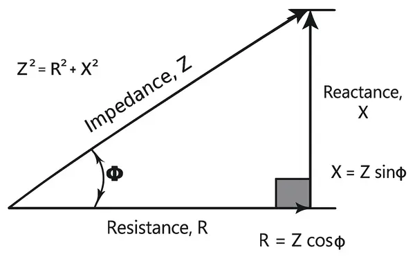
The X/R ratio, which is the ratio of the reactance (X) to the resistance (R) in an AC circuit, is the tangent of the phase angle meaning
X R = tan(ø)
The phase angle (ø) itself is then found by taking the arctangent (inverse tangent) of this ratio:
ø = tan-1( X R )
Causes of X/R – Why it occurs in Electrical System
High Inductance:
Inductors resist changes in current. Systems with more inductance (like transmission lines, transformers, and large motors) have a higher reactance (X). More reactance means a stronger and longer-lasting DC offset during a fault.
Sudden Change in Current:
When a short circuit occurs, the system current attempts to alter immediately. However, with an inductive circuit, current cannot change instantly, resulting in a DC offset in the waveform. The system effectively recalls the prior current and attempts to withstand the rapid jump.
Low Resistance:
When resistance is low compared to reactance, the current doesn’t have a quick path to decay. This means the DC offset decays slowly, leading to a higher initial peak current during the short circuit.
Now that we’ve seen where the X/R ratio comes from, let’s explore the consequences it brings during a short circuit
Effects of X/R on Short Circuit:
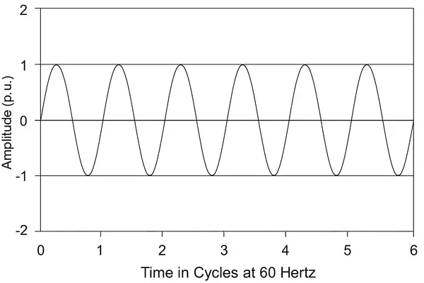
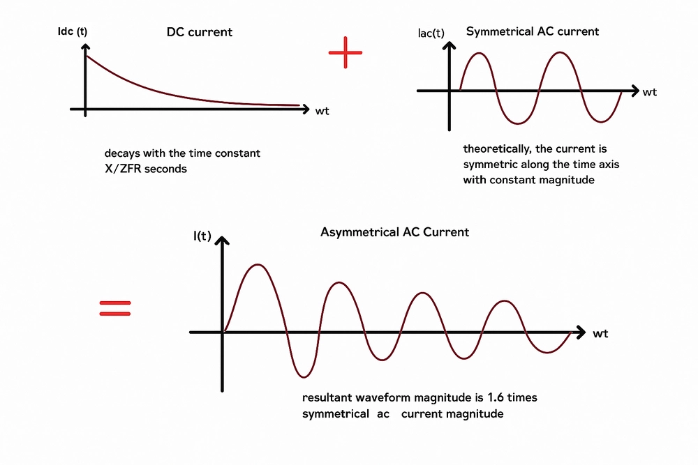
When a short circuit happens in a power system, the current that flows isn’t always smooth and predictable. The total fault current is made up of two parts: the symmetrical current and the asymmetrical current.
If the positive and negative peaks of the current waveform are symmetrical around the zero axis the waveform is called symmetrical, whereas if the positive and negative peaks of current waveform are not symmetrical around the zero axis the waveform is called asymmetrical.
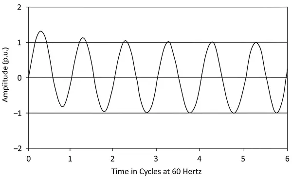
When a short circuit appears in an electrical system, the current does not just jump to a stable value; it varies quickly. This unexpected shift upsets the balance of the AC waveform, particularly in systems that are primarily inductive. The system responds to this abrupt disturbance by causing a brief change in the current waveform known as the DC offset.
DC Offset:
The DC offset is a non-symmetrical component that gets added to the regular sinusoidal fault current immediately after a short circuit. It causes the current waveform to become unbalanced. This offset is not permanent; it decreases over time, but both its magnitude and duration are directly proportional to the system's X/R ratio.
The behavior of the current during and after a short circuit can be broken into three distinct stages, all of which are tied to how the DC offset plays out
- Sub-Transient State
- Transient State
- Steady State
Sub-Transient State:
This is the initial phase, lasting only a few milliseconds. Here, the current is at its highest, and the DC offset is at its peak. It occurs right after the fault and is dominated by the internal sub-transient reactance of generators, motors, and transformers.
Transient State:
In this phase, the current starts to decrease, but it's still influenced by the lingering DC offset. The waveform is beginning to return to a balanced sinusoidal shape but hasn't fully settled yet. This stage may last several cycles
Steady State:
This is the final stage, where the DC offset has fully decayed, and the current becomes a pure symmetrical AC waveform. This steady-state fault current is what the system would deliver continuously if the short circuit weren’t cleared
The X/R ratio of the system's reactance (X) to resistance (R) determines the duration of each of these stages.
A high X/R ratio indicates more inductance and less resistance in the system. Because inductance resists current changes and resistance helps to dissipate energy, a high X/R ratio causes the DC offset to decrease slowly, extending the Sub-Transient and Transient periods. In high X/R systems (like transmission lines, generators, or transformers), the DC offset can persist for several cycles, sometimes up to 10 or more, depending on system design. This extends the period of high asymmetrical current.
In contrast, a lower X/R ratio (greater resistance) permits the system to discharge stored energy more quickly, resulting in a shorter DC offset. This results in shorter Sub-Transient and Transient durations, allowing the current to reach steady state more quickly. In low X/R systems (such as short cable runs or resistive loads), the offset fades quickly, sometimes within 1–2 cycles, resulting in a faster return to symmetrical current.
Furthermore, the moment when the fault occurs on the AC waveform, known as the point-on-wave, influences the initial value of the DC offset. If the fault occurs at a current zero crossing, the DC component will be at its peak, amplifying the first Sub-Transient current spike.
Impact on Protective Devices
One of the most important consequences of a high X/R ratio is a rise in peak asymmetrical current during a short circuit, particularly in the initial few cycles, when preventive devices must react quickly. Circuit breakers are extremely sensitive to such early fault circumstances. A breaker is built with particular making, breaking, and resisting capacities, all of which are tested using common assumptions regarding peak fault current. However, when the X/R ratio is higher than expected, it can have a direct impact on the DC component of fault current. A higher X/R ratio produces a larger and more lasting DC offset, resulting in a more asymmetrical current waveform during faults. This DC offset rises the peak current, typically exceeding the breaker's rated capacity. If not treated properly, it can result in breaker failure, delays in operation, or even catastrophic equipment damage. That is why understanding the X/R ratio is crucial for short-circuit studies and selecting protective devices.
Thermal and Mechanical Stress on Equipment:
The effects of X/R ratio are not limited to protective equipment. Asymmetrical fault currents cause increased mechanical and thermal stress on motors, transformers, and generators. The first peak current, especially when combined with a large DC offset, generates powerful forces within the windings and rotor of rotating devices.
This rapid shock can physically stress the components, causing wear and tears, distortion, and even internal flaws if the stress exceeds the design limitations. Thermally, higher currents generate more heat, particularly during longer-duration faults. Over time, repeated exposure to large asymmetrical currents can reduce the life of electrical machinery and insulating systems.
Understanding the implications of the X/R ratio is critical for performing precise short circuit analysis. It's more than simply a technical number; it influences how fault currents behave, how protection systems react, and how equipment performs under stress. Designing for real-world fault scenarios requires considering both symmetrical and asymmetrical current, accounting for DC offset, and ensuring that all components are appropriately rated.
Correlation Between Tested X/R Ratio and Short Circuit Rating:
In short circuit studies, the X/R ratio plays a crucial role in identifying the peak asymmetrical fault current. Knowing the tested X/R ratio is crucial when comparing the fault current to the electrical device ratings. The electrical equipment is acceptable if the calculated symmetrical current and X/R ratio are both within acceptable limits.
| Equipment Type | Rating Range | X/R | PF | S2P | Standard |
|---|---|---|---|---|---|
| Panelboards | < 10 kA | 1.732 | 0.5 | 1.645 | UL 67 |
| 10-20 kA | 3.18 | 0.3 | 1.941 | UL 67 | |
| > 20 kA | 4.899 | 0.2 | 2.159 | UL 67 | |
| MCC | < 10 kA | 1.732 | 0.5 | 1.645 | UL 845 |
| 10-20 kA | 3.18 | 0.3 | 1.941 | UL 845 | |
| > 20 kA | 4.899 | 0.2 | 2.159 | UL 845 | |
| Switchboards | < 10 kA | 1.732 | 0.5 | 1.645 | UL 891 |
| 10-20 kA | 3.18 | 0.3 | 1.941 | UL 891 | |
| > 20 kA | 4.899 | 0.2 | 2.159 | UL 891 | |
| Switches | < 10 kA | 1.732 | 0.5 | 1.645 | UL 1008 |
| 10-20 kA | 3.18 | 0.3 | 1.941 | UL 1008 | |
|
|
> 20 kA | 4.899 | 0.2 | 2.159 |
UL 1008 |
| Switchgear | General | 6.591 | 0.15 | 2.292 | ANSI C37.50 |
| MCCB | < 10 kA | 1.732 | 0.5 | 1.645 | UL 489 |
| 10-20 kA | 3.18 | 0.3 | 1.941 | UL 489 | |
| > 20 kA | 4.899 | 0.2 | 2.159 | UL 489 | |
| ICCB | < 10 kA | 1.732 | 0.5 | 1.645 | UL 489 |
| 10-20 kA | 3.18 | 0.3 | 1.941 | UL 489 | |
| > 20 kA | 4.899 | 0.2 | 2.159 | UL 489 | |
| PCB | General | 6.591 | 0.15 | 2.292 | UL 1066 |
| (Fused) | 4.899 | 0.2 | 2.159 | UL 1066 | |
| Fuses | < 10 kA | 1.732 | 0.5 | 1.645 | UL 248-1 |
| > 10 kA | 4.899 | 0.2 | 2.159 | UL 248-1 | |
| HV/MV Switchgear | (kA Rating Basis) | 17.0 | 0.0587 | 2.59 | ANSI.C37.09-1999 |
| (MVA Rating Basis) | 15.0 | 0.0665 | 2.561 | ANSI.C37.010-1979 | |
| MV E2 Motor Starter | General | 15.0 | 0.0665 | 2.561 | UL 347 |
| HV/MV Power Fuses | General | 15.0 | 0.0665 | 2.561 | ANSI C37.41 |
Precautions for high X/R Ratio in Power System:
Designing a power system implies not only handling routine operational loads, but also preparing for rare but intense incidents such as short circuits. The X/R ratio is one of the most important factors in short circuit analysis because it determines the size and duration of the fault current peak. When the X/R ratio is high, the first current spike caused by DC offset increases significantly, posing a problem for both safety and equipment design. To ensure system safety, numerous safeguards must be implemented throughout the planning and design stages.
At Allumiax we use advanced modeling tools like ETAP and SKM Power Tools to make accurate decisions. These tools simulate electrical networks, identify X/R ratios at various points, and model short-circuit events. We also aid in protection coordination, ensuring that breakers, relays, and fuses work together even during severe faults caused by DC offset.
In conclusion, properly accounting for the X/R ratio in power system design is crucial for maintaining both safety and reliability. By selecting the right circuit breakers and protection devices, engineers can ensure that systems can handle high fault currents without failure. Utilizing ETAP and SKM Power Tools allows for accurate simulation and protection coordination, ensuring that breakers, relays, and fuses respond correctly under severe fault conditions.
Engineers at Allumiax adhere to industry standards and codes to ensure compliance with safety regulations. These precautions help prevent damage to equipment, reduce downtime, and optimize system performance. Ultimately, addressing the X/R ratio during the design phase results in a more resilient and reliable power system capable of managing both typical and extreme fault scenarios. Contact AllumiaX today. Our team of experienced engineers and technicians are ready to provide tailored solutions for your power system studies.


Abdur Rehman, PE
Author
Abdur Rehman is a professional electrical engineer with more than eight years of experience working with equipment from 208V to 115kV in both the Utility and Industrial & Commercial space. He has a particular focus on Power Systems Protection & Engineering Studies....
He earned his BSEE & MSEE from Washington State University in 2013 & 2017 respectively and an Engineering Technology Management degree in 2021.
Abdur Rehman is the CEO and co-founder of allumiax.com and creator of GeneralPAC by AllumiaX. He has been actively involved in various roles in the IEEE Seattle Section, IEEE PES Seattle, IEEE Region 6, and IEEE MGA.
Abdur Rehman is a board member of CordobaAcademy.org and enjoys local community volunteering. All AllumiaX blogs are special because of his love to share knowledge in the most intuitive way possible.
Stay Sharp & Join our Mailing List!
Subscribe to Allumiax Blog for updates on power system studies, tips, guides and insights on electrical engineering from industry leaders.

Recent Posts

Stay Sharp & Join our Mailing List!
Subscribe to Allumiax Blog for updates on power system studies, tips, guides and insights on electrical engineering from industry leaders.