Lossless Transmission Line, Characteristic Impedance and Surge Impedance Loading

For the development of our society, it is essential to have a natural tendency to make things around us more efficient. The reason behind this eagerness is everything in the world is limited. So, the only way to ensure our sustainable development is to prolong the life of these natural resources by making our systems more efficient. Similarly, when it comes to electrical power systems, specifically power transmission lines, it’s our best bet to make them as efficient and lossless as we can. However, it is easier said than done.
Talking about transmission lines, they have four primary line constants i.e. resistance (R), inductance (L), capacitance (C) and conductance (G). These parameters are distributed along the line, hence also called distributed parameters. Primary constants represent conductor resistance & inductance along with insulator capacitance & conductance in a transmission line. They describe the characteristics of a transmission line in terms of electrical properties and are different from secondary constants.
Secondary constants of a transmission line are referred to as characteristic impedance (Zo) and propagation constant (γ) which can be derived from primary constants. Though these parameters are generally applicable to all types of transmission lines, they also help us in understanding phenomena like reflections and wave propagation along a power transmission line.
The main motive behind this article is to walk you through the important parameters and phenomena involved in a transmission line, and what role do these parameters play in achieving an almost lossless transmission line?
Lossless Transmission Line
Although it is practically impossible to design a lossless transmission line, we can minimize losses by considering parameters like characteristic/surge impedance (Zo). But before diving into these parameters, we should have a look at what really is the idea behind lossless transmission lines and why is it so important in power system analysis.
What is a Lossless Transmission Line?
A transmission line having no line resistance or no dielectric loss is said to be a lossless transmission line. It means that the conductor would behave as a superconductor and dielectric would be made of perfect dielectric medium. In a lossless transmission line, power sent from a generating point would be equal to power received at the load end. There is no power dissipation in the line itself.
Significance of a Lossless Transmission Line in Power System Analysis
A question comes to mind that if it is practically impossible to model a lossless transmission line then why should we study them in theory? Well, because it helps us develop a deep understanding of low-loss and high frequency transmission lines which physically exist in our real world. Their studies and analysis offer more generic equations and simplified approximations which can be considered when analyzing real transmission lines.
Characteristic Impedance (Zo)
As we already discussed that primary constants are very significant in transmission lines, they make characteristic impedance (Zo) a very significant parameter as well, because characteristic impedance (Zo) involves all four of the primary constants in its expression which we will be discussing sooner in this article. But before we do that, it is essential for us to have a clear idea of what uniformity means in a transmission line? Because it is an important terminology in the subject matter and often confused at times.
What is a Uniform Transmission Line?
A transmission line with a constant V/I ratio throughout the whole length and uniformly distributed primary constants along the whole line is said to be a uniform transmission line.
What is Characteristic Impedance?
Characteristic impedance can be defined as the ratio of amplitude of voltage to the amplitude of current of a unidirectional wave travelling from source to load along a uniform transmission line in the absence of reflections.
It may also be defined as a square root of the ratio of series impedance of a line to its shunt admittance.
Where,
Z = R + jwL (series impedance per unit length per phase)
Y = G + jwC (shunt admittance per unit length per phase)
R, L, G and C are the primary constants of a transmission line, and the above expression confirms that characteristics of a transmission line are described by primary line constants.
Characteristic Impedance of a Lossless Transmission Line (Surge Impedance)
Characteristic impedance of a lossless transmission line is called surge impedance. In a lossless transmission line, the resistance(R) and conductance(G) are zero; hence its characteristic impedance becomes,
Above is the expression for surge impedance. A transmission line with losses has a complex number as its characteristic impedance whereas lossless transmission lines have a real characteristic impedance.
Role of Characteristic Impedance in Infinite Transmission Lines
A line (lossless or lossy) is said to be infinite if it terminates in its characteristic impedance. Or to put things more descriptively, a line with finite length may seem infinite to the source if its terminating impedance (impedance at which a line is terminated) is equal to its characteristic impedance. The reason for this seemingly infinite length is that the load appears infinitely away to the source because the source receives no reflections (to be discussed in reflection coefficient).
Energy supplied along such lines are not reflected. These lines have Input impedance equal to their characteristic impedance which is physically achieved by using a line terminator having impedance equal to the characteristic impedance of the line.
Surge Impedance Loading (SIL)
Now that we have discussed Lossless transmission line and surge Impedance, we are good to go towards our final topic of this section that is surge impedance loading (SIL).
What is Surge Impedance Loading?
When a transmission line is loaded in such a way that it is terminated in its surge impedance, the loading on that transmission line is called Surge Impedance Loading. In simple words, surge impedance loading is the maximum load that can be fed from a lossless transmission line. SIL helps us in determining the maximum loading limit that can be delivered by a transmission line. At SIL, the reactive power generated by the capacitive reactance is absorbed by the inductive reactance of the line so the net reactive power through the transmission line becomes zero and power is delivered at unity power factor. Hence the line is considered to be loaded with purely resistive load.
∵ inductive VAR = capacitive VAR
The above equation is the characteristic impedance of a lossless transmission line. It means that if the total capacitive VAR is completely absorbed by inductive VAR of the line, then that transmission line can be called lossless because it exhibits characteristic impedance of a lossless transmission line.
SIL can be mathematically expressed as,
Where,
kVLL = line to line voltage of a transmission line in kV
Zo = characteristic impedance of a transmission line in ohms
Reflections and Standing Waves on a Transmission Line
Besides characteristic impedance, the phenomenon of signal reflection in transmission lines also needs to be discussed in this article.
What are Reflections in a Transmission Line and what causes them?
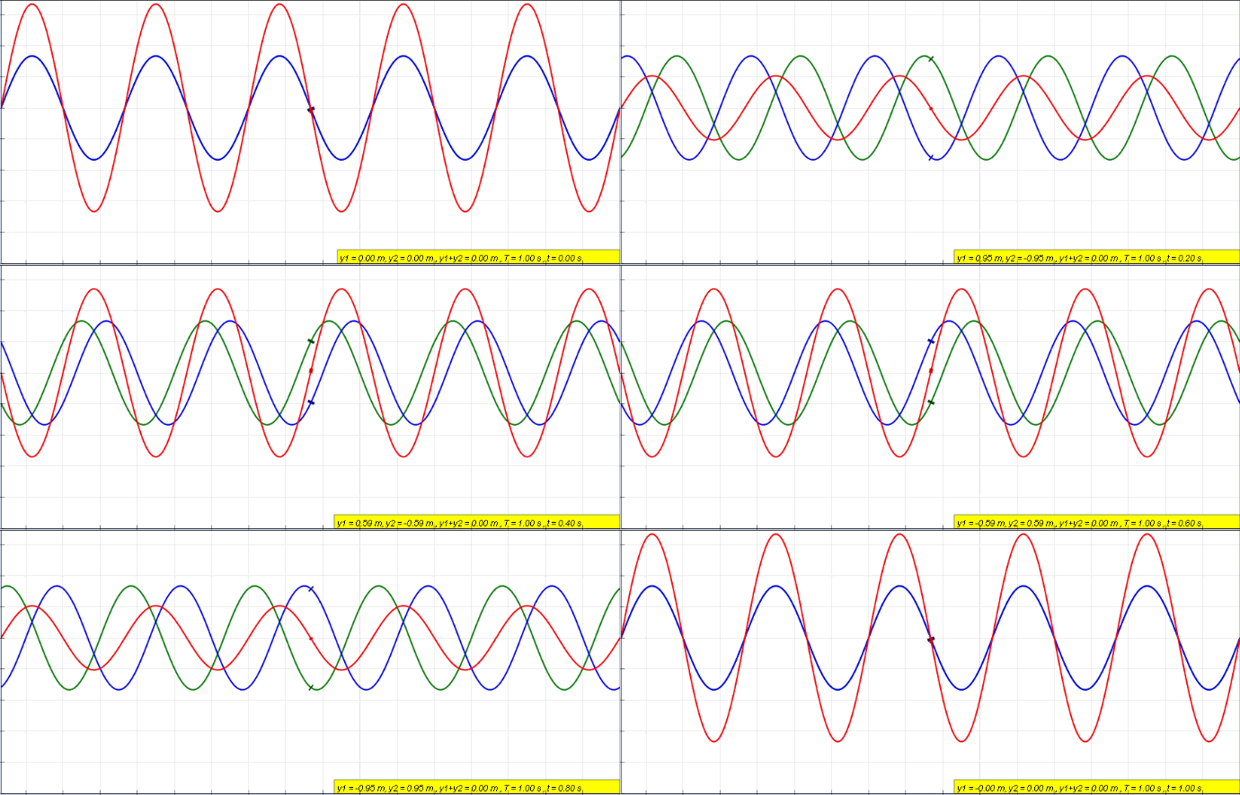
Reflections are nothing but reflected incident waves when a transmission line has discontinuous impedance (mismatched impedance). In other words, if a line is not uniform throughout the whole length, the incident wave (i.e., signal sent from source to load) will reflect to its origin (source) instead of travelling all the way to the far end (load). This is what they call reflections. These reflections are opposite to the incident waves, and they have adverse effects on a transmission line such as, generating standing waves on the line, attenuation in travelling waves (incident waves), and as a result, power loss in transmission lines. There will be no reflections and no standing waves on a transmission line if it is terminated in its characteristic impedance.
Green signal = incident wave
Blue signal = reflected wave
Red signal = standing wave (they are generated due to interference between incident and reflected wave along a line)
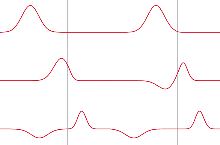
When a transmission medium through which a wave is travelling changes, it experiences partial transmittance and partial reflectance. This behavior of waves is best explained by reflection and transmission coefficient.
What is Reflection Coefficient?
It is a parameter that describes how much of an incident wave is being reflected due to impedance discontinuity in a transmission line. It is denoted by capital gamma (Γ) and can be calculated by the ratio of the amplitude of reflected wave to the amplitude of incident wave.
Reflection coefficient can be mathematically represented by,
Where, V ─ & I ─ represent voltage & current of the reflected wave, and V + & I + represent voltage & current of the incident wave respectively.
The above expression gives the measure of reflectance that takes place when a travelling/incident wave experiences a change in the transmission medium.
Now, if a transmission line is terminating at a load impedance of ZL and has characteristic impedance of Zo then the expression becomes,
V = ZL ─ Zo & V + = ZL + Zo
For an infinite transmission line, terminating impedance (ZL) is equal to its characteristic impedance (Zo).
Mathematically,
ZL = Zo
Γ = 0
The above calculation proves that there are no reflections in a transmission line when it is terminated in its characteristic impedance.
What is Transmission Coefficient?
It is a parameter that describes how much of an incident wave is being transmitted when the impedance of a transmission line is discontinuous. It is the ratio of the amplitude of transmitted wave to that of the incident wave. It explains the amount of transmittance that takes place when a travelling wave experiences a change in the transmission medium. Transmission coefficient of an infinite transmission line is maximum because the incident signal is completely transmitted without any reflections.
The black line indicates the change in a transmission medium. The first wave is an incident wave. After it reaches the point at which the transmission medium changes, it splits into two waves. The wave that propagates through the black line or travels towards the right indicates partial transmittance, and the wave that reflects back or travels to the left of black line indicates partial reflectance.
Standing Waves and their Effects on a Transmission Line
Standing waves are voltage or current waves and are result of interference between incident and reflected waves along a line. The reason why they are called standing waves is because they are stationary and do not propagate along the line. The point of maximum amplitude on a standing wave is called an antinode and the minimum amplitude point is called node.
Standing waves with high amplitude are detrimental for transmission lines. Voltage antinodes of high amplitude standing waves damage insulation and current antinodes cause overheating and mechanical breakdown of transmission lines.
Transmission lines are prone to several issues which cause poor power quality and produce electrical transients. Engineers at AllumiaX have profound understanding of these problems and how to resolve them. In case you are concerned with poor power quality in your power system, or you want to get rid of several transients, contact us and avail our services. We provide both transient stability and power quality study.

Stay Sharp & Join our Mailing List!
Subscribe to Allumiax Blog for updates on power system studies, tips, guides and insights on electrical engineering from industry leaders.


