Understanding Grounding Systems for Electrical Safety
Whether you’re operating a facility, designing a new power network, retrofitting an existing system or troubleshooting recurring electrical issues, understanding grounding and neutral systems is essential for safe and reliable operation.
In this blog, we will focus on areas where grounding is crucial and where mistakes can sometimes be costly, such as, transformer secondary grounding, asymmetrical faults, grounding methods, and NGR (Neutral Grounding Resistor) selection.
Why Grounding Matters
Grounding is important because it provides a stable reference point for system voltages, it controls transient over voltages, and it ensures that when a fault occurs, it is detected and cleared promptly. Without a proper grounding system where necessary, the following may be the outcomes
- Faults are harder to detect
- Equipment damage becomes more severe
- Arc flash hazards increase
- Voltage instability
- Personnel safety is compromised
Therefore, grounding should not be treated as optional or unnecessary.
Types of Faults in Power Systems
Power system faults can be divided into two broad categories depending how frequently they occur and how severe of a damage they deal.
Frequent Faults
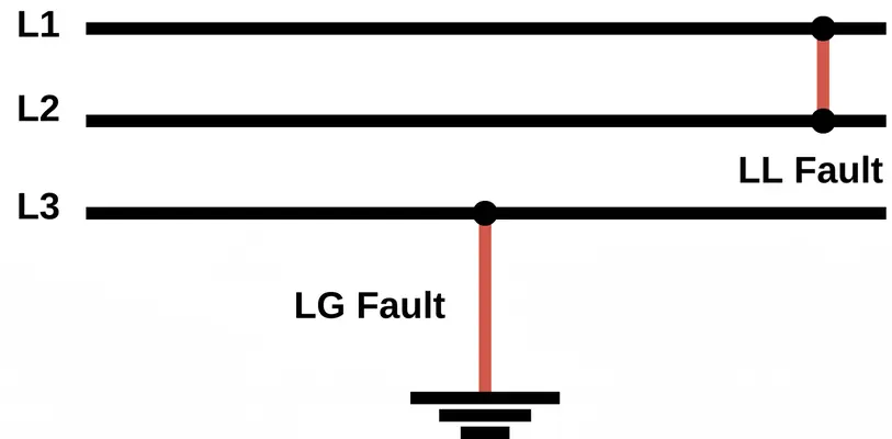
- Single line-to-ground (L-G), Most common, 70–80% of all faults
- Line-to-line (L-L), 10–15% of all faults
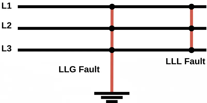
- Double line-to-ground (L-L-G), 5–10% of all faults
Infrequent Faults
- Three-phase (balanced) faults, 2–5% of all faults
- Three-phase-to-ground faults, <1–2% of all faults
These faults may be rare, but they are the most severe ones,
Once we understand the type of faults a system will likely experience, then we can move towards the suitable grounding method for that system.
Asymmetrical Faults and Why They Matter
Asymmetrical faults are those in which the phases are affected unevenly, such as line-to-ground, line-to-line, or double line-to-ground faults. Faults which involve ground need a return path through the ground to the system neutral, which decides how much zero-sequence current flows and how severe the fault appears on the protective devices.
During an asymmetrical fault, the system experiences:
- Large DC offset
- Unbalanced phase currents
- Negative- and Zero-sequence components
- Higher peak fault currents
These directly influence relay timing, transformer, and the effectiveness of ground-fault detection.
Grounding Systems in Power Networks
There are several grounding philosophies used globally:
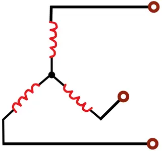
Solidly Grounded
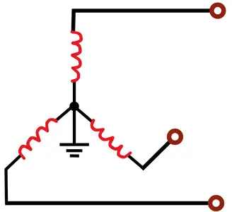
Solidly Grounded system has the neutral directly connected to earth without any sort or intentional resistance. This results in high ground-fault currents due to which we get very fast fault clearing. But high fault current also means that we will get high arc-flash energy and stress on cables and switchgears making it less desirable where equipment safety is a priority. This is chosen for simple protection coordination, minimal transient over voltages and compliance with code.
Resistance Grounding (NGR Systems)
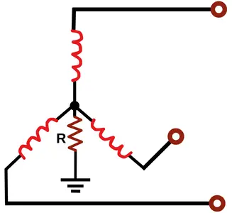
Neutral Grounding resistors are chosen of a precise value needed for a particular power system to suit the fault clearing sensitivity and equipment protection.
Types of Neutral Grounding Resistors:
| Aspect of comparison | High Resistance Grounding | Low Resistance Grounding |
|---|---|---|
| Typical ground fault currents | 5–10 Amps | 50–400 Amps |
| Arc-flash energy levels | Very low | Low but higher than HRG |
| Mechanical & thermal stress on equipment | Minimal | Moderate |
| Response to first L-G fault | no immediate trip (Alarm only) | Trip of the faulty feeder |
| Continuity of service | System continues operating during a single L-G fault | Faults are cleared quickly; continuity is not maintained |
| Effect of system capacitance | Must be low, so resistor dominates the fault path | Suitable for high system capacitance |
| Typical application | process plants, data centers, hospitals etc. | Industrial MV networks, utilities etc. |
How to Choose an NGR (And Why It Matters)
Choosing an NGR depends on:
- Desired ground-fault current: Sets the magnitude of desired fault current according to the system requirements. If it’s too low, relays may not detect the fault and if it’s too high, equipment may stress and result in higher arc-flash energy.
- System voltage: Determine the voltage across the NGR during a fault, this affects resistor sizing and insulation requirements.
- Allowable arc-flash energy: Choose the NGR value which limits the potential energy released during a fault, enhancing personnel safety.
- Relay pickup and coordination: Choose the NGR value which ensures ground-fault currents are high enough for relays to operate reliably and selectively.
- Transformer neutral insulation: NGR must prevent excessive voltage across the neutral, protecting insulation.
Too small = fault not detected
Too large = equipment damage, higher arc flash
This is why facilities often request NGR sizing studies before commissioning. At AllumiaX, we provide expert NGR sizing, selection, and design services to ensure optimal protection, operational continuity, and safety for industrial and utility networks.
Reactance Grounding

Reactance grounding uses a grounding reactor to limit ground-fault current, without the thermal energy dissipation like that of resistance grounding. Reactance grounding is used for systems where capacitive charging currents are high because it provides reactance to the system and increases the lagging current and neutralizes the capacitive currents. While it may be more rigid and offer low fault energy, its poor damping of transient overvoltage and protection challenges have made it obsolete.
Ungrounded Systems
Ungrounded or floating systems have no intentional connection to earth. In the event if a fault it allows operation on the first Line to Ground fault since the fault current is limited. Being ungrounded and having no zero reference, dangerous transient overvoltage can occur during switching, faults and even by the line to ground capacitance as it provides a small neutral current path.
Every grounding method involves trade-offs, and the optimal choice depends on load characteristics, equipment sensitivity, utility requirements, and safety goals. The grounding point is also equally important, which must be planned carefully to ensure reliable system behavior.
Why Transformer Secondary Grounding Is Essential
The transformer secondary is often the practical neutral grounding point because:
- It provides a defined reference for system voltages
- It allows detection and clearing of ground faults
- It stabilizes transient overvoltage
- It enables proper relay coordination
If transformer secondary is not grounded, fault currents may return through uncontrolled paths, leading to overvoltage, equipment damage or protection maloperation. To understand how these fault currents behave, we must know the difference between residual currents and asymmetrical currents.
Residual Current vs Asymmetrical Current
Residual Current
Iresidual = Ia + Ib + Ic
Used for:
- Earth-fault relays
- Ground-fault CTs
- Leakage monitoring
Residual Current sums the actual phase currents (Ia + Ib + Ic) to detect leakage or ground faults.
Asymmetrical Current
I = I1 + I2 + I0
Used for:
- Identifying fault type and severity.
- Monitoring negative-sequence currents in generators and motors
- Enabling selective coordination
Asymmetrical Current sums the mathematical symmetrical components (I = I1 + I2 + I0) of a phase current to analyze unbalanced faults.
Protection against Asymmetrical and Residual currents:
| Aspect of comparison | Residual Currents | Asymmetrical Currents |
|---|---|---|
| Typical ground fault currents | Earth leakage, indirect contact, insulation degradation, moisture, rodents etc. | L–G, L–L–G, and severe unbalanced system faults |
| Nature of Currents | Small leakage currents flowing to earth due to insulation failure or contact | High-magnitude fault currents with DC offset and unbalanced phases |
| Detection of fault | Detection of leakage or imbalance between phase and neutral | Detection of current magnitude, direction, sequence components, and waveform asymmetry using CTs |
| Protective Devices | ELCB (voltage-based detection) and RCCB (current imbalance detection) | Overcurrent relays, directional earth-fault relays, zero-sequence CT–based ground-fault relays, differential relays, and distance relays etc. |
| Primary Purpose of PD | Protection of personnel against electric shock and leakage faults | Protect equipment and maintain system stability |
| Coverage | Only covers leakage-level faults | Covers severe and complex fault conditions |
| Application | Residential, commercial, and low-voltage installations | Industrial plants, substations, and transmission networks |
Choosing the Right Grounding Method for Your Facility
No grounding system is universally perfect, but it must align with:
- System voltage
- Fault characteristics
- Equipment sensitivity
- Arc flash mitigation strategy
- Operational continuity requirements
- Industry standards
- Utility interconnection rules
Standards & Codes for Grounding and NGR Selection
The grounding method and NGR selection should follow recognized international and national standards to ensure safety, equipment protection, and operational reliability. Some of the key references include:
- IEEE guidelines (e.g., C62.92 series for grounding and C57.32 for neutral grounding devices)
- NEC/NFPA 70 for electrical safety requirements in the U.S.
- IEC 60364 for international grounding practices
These standards provide guidance on selecting grounding methods, coordinating protective devices, and sizing neutral grounding devices. At AllumiaX, we apply these standards in our grounding studies, NGR sizing, relay coordination, and system design to ensure that every electrical network we work on is safe, reliable, and compliant.
Grounding is more than just connecting a conductor to earth, it is a key engineering decision that affects safety, system stability, equipment life, arc-flash risk, and operational continuity.
Whether you're dealing with asymmetrical faults, NGR selection, or transformer secondary grounding, a well-planned grounding system ensures your facility stays safe, reliable, and compliant.
At Allumiax, we perform comprehensive power engineering studies including ground grid studies with step and touch potential evaluation, NGR sizing, relay coordination, short-circuit analysis, arc flash analysis, transient stability studies and more. If your facility needs a grounding review or if you’re designing a new system, our engineers are ready to help.
Request a quote today to discuss your requirements.


Abdur Rehman, PE
Author
Abdur Rehman is a professional electrical engineer with more than eight years of experience working with equipment from 208V to 115kV in both the Utility and Industrial & Commercial space. He has a particular focus on Power Systems Protection & Engineering Studies....
He earned his BSEE & MSEE from Washington State University in 2013 & 2017 respectively and an Engineering Technology Management degree in 2021.
Abdur Rehman is the CEO and co-founder of allumiax.com and creator of GeneralPAC by AllumiaX. He has been actively involved in various roles in the IEEE Seattle Section, IEEE PES Seattle, IEEE Region 6, and IEEE MGA.
Abdur Rehman is a board member of CordobaAcademy.org and enjoys local community volunteering. All AllumiaX blogs are special because of his love to share knowledge in the most intuitive way possible.
Stay Sharp & Join our Mailing List!
Subscribe to Allumiax Blog for updates on power system studies, tips, guides and insights on electrical engineering from industry leaders.

Recent Posts

Stay Sharp & Join our Mailing List!
Subscribe to Allumiax Blog for updates on power system studies, tips, guides and insights on electrical engineering from industry leaders.