Simple Method for Basic Short Circuit Current Calculations
In order to dig deep into the easy way to calculate the short circuit current calculations, we must first develop our knowledge base on the basics of short circuit analysis.
"A Short Circuit current analysis is used to determine the magnitude of the short circuit current which the system is capable of producing and compares the magnitude of the short circuit magnitude with the interrupting rating of the overcurrent protective devices (OCPD)."
In the previous blog, we gave you a brief introduction to "Short circuit Analysis". If you haven't checked it out yet, please read that blog and then come back to this one!
A basic electrical theorem says that the short circuit current actually depends upon the two most important parameters:
- The total impedance from the source to the point of the fault
- The nominal voltage of the system
With the help of the basic formula, we can easily calculate the short circuit current at the fault location, and with the help of those values, we can analyze the system and install protective devices and protect the facility from any major harm or damage.
I_fault = V / Z
There are many methods to calculate the short circuit currents, however, we will give you the basic idea of how we can calculate the short circuit currents in a simple AC distribution system.
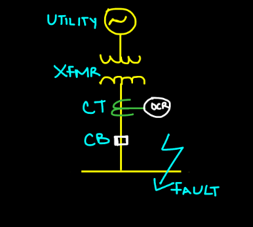
Please consider a Single Line Diagram (SLD) with a power utility, transformer, and an overcurrent protective device (OCPD) having a specific short-circuit current interrupting rating.
Hello there! On a related topic, we previously wrote a blog about Short Circuit Current Calculations – Infinite bus method. If this peaks your interest, check it out and let us know what you think
Let's talk about the power source first. Usually, we consider the power source or utility as an infinite capacity or "The source has an infinite bus."
All that is being said is the source voltage has no internal impedance. As a result, a simple calculation becomes very conservative. Since the source has been assumed to have no impedance of its own, the corresponding short-circuit current will be the worst-case scenario.
Now, the next thing we have in our One Line diagram is the transformer. The impedance determining the amount of short-circuit current on its secondary side of the transformer is made up of two separate impedances:
"Its own impedance plus the impedance of the cable that is connected between the utility and transformer. The transformer's own impedance is the amount of its opposition to the flow of short-circuit current through it."
Now, all transformers have impedance, and it's generally expressed as a voltage percentage. This is the percentage of normal rated primary voltage that must be applied to the transformer to cause full-load rated current to flow in the short-circuited secondary.
What does this mean? and why is it important to the simple calculation?
Suppose, if we have a 480 V/220 V step-down transformer which has an impedance of 5%, this means that 5% of 480 V i.e. 24 V, applied to its primary side will cause rated load current flow in its secondary.
If 5% of primary voltage will cause such current, then 100% of primary voltage will cause 20 times (100 divided by 5) full-load-rated secondary current to flow through a short circuit on its secondary terminals.
Obviously, then, the lower the impedance of a transformer of a given kVA rating, the higher the amount of short-circuit current it can deliver.
Now that we understand the basic variables that determine the short-circuit currents, let's do a simple calculation for the same One Line diagram that is mentioned above.
Suppose we have a simple distribution system comprising of the following components:
- Power utility that is providing power to the system
- Step-down transformer to transform the voltage level
- Current transformer for stepping down the current level that is later being fed to the relay
- Relay for protection purposes that will give the signal to the Circuit breaker under any abnormal condition. Check out Power System Protection Fundamentals Course in which we briefly discussed "Types of protective relays & design requirements".
Consider there is a short circuit fault on the main bus. For the sake of clarity and simplification, let's assume there are negligible line impedances between the transformer secondary and the fault.
At the time of the fault, the CT will determine the amount of current which is flowing through the secondary side of the transformer which results in an overcurrent relay (OC Relay) to act immediately and give the signal to the connected Circuit Breaker which will eventually open its contacts and save the working personnel from any injuries. In this way, the system that is connected to the downstream of that bus will be protected.
So in order for the proper working of all these protective devices, we need to determine 2 things.
- Determine full load secondary current (Isec)
- Determine the Short circuit current value on the secondary side of the transformer (Isc)
In order to do this, we will use a simple formula Suppose the utility has a power rating of 100 KVA and an impedance value of 2.5% and we already know that the 220 volts are available on the secondary side of the transformer. So,
I_sec = (KVA rating of the Source) / (Secondary side voltage of the Transformer)
By plugging the values, we will get;
I_sec = 100000 / 220
Now, we will calculate the value of the short circuit current on the secondary side of the transformer, it will help the protective device to act accordingly.
I_sc = ((100%) / ((Impedance of Transformer (Z%))) * I_sec
By plugging the values, we will get;

I_sc = (100 / 2.5) * 454.54
I_sc = 18181.6 Amps
Or, 18.18 KA. It means that the protective device that we will use must have a short circuit capacity of more than 20 KA. It will help the Over Current Protective device (OCPD) to safely interrupt this amount of fault current.
This blog has just provided you a basic idea of how we will calculate the amount of short circuit current for a small power system.
In a future blog (related to Short circuit), we will go deep and explain every single aspect of calculating the short circuit currents in a single-phase and three-phase power system.
I hope, you will like this blog and also recommend it to others. If you have any questions, please feel free to ask in the comments section.


Abdur Rehman, PE
Author
Abdur Rehman is a professional electrical engineer with more than eight years of experience working with equipment from 208V to 115kV in both the Utility and Industrial & Commercial space. He has a particular focus on Power Systems Protection & Engineering Studies....
He earned his BSEE & MSEE from Washington State University in 2013 & 2017 respectively and an Engineering Technology Management degree in 2021.
Abdur Rehman is the CEO and co-founder of allumiax.com and creator of GeneralPAC by AllumiaX. He has been actively involved in various roles in the IEEE Seattle Section, IEEE PES Seattle, IEEE Region 6, and IEEE MGA.
Abdur Rehman is a board member of CordobaAcademy.org and enjoys local community volunteering. All AllumiaX blogs are special because of his love to share knowledge in the most intuitive way possible.
Stay Sharp & Join our Mailing List!
Subscribe to Allumiax Blog for updates on power system studies, tips, guides and insights on electrical engineering from industry leaders.

Recent Posts

Stay Sharp & Join our Mailing List!
Subscribe to Allumiax Blog for updates on power system studies, tips, guides and insights on electrical engineering from industry leaders.