Neher Mcgrath Study of Cables in Power System

The Neher-McGrath calculation is a technique for calculating the temperature increase brought on by electrical current flow in conductors. It is highly regarded and utilized in the field of electrical power systems and is based on the laws of thermodynamics and electrical engineering concepts. By aiding in the prevention of overheating and probable conductor failure, the Neher-McGrath calculation is a crucial instrument for assuring the safe and effective operation of electrical systems.
Background of Neher McGrath Study
The cables that network a power system together form the backbone of the system. It is only logical, therefore, that any complete analysis of a power system should include an analysis of its cable ampacities. This analysis is complicated since the ampacity of a conductor varies with the actual conditions of use.
As stated in NFPA 70 NEC Article No. 100, Ampacity is “the current in amperes a conductor can carry continuously under the conditions of use (conditions of the surrounding medium in which the cables are installed) without exceeding its temperature rating.”
Therefore, a cable ampacity study is the calculation of the temperature rise of the conductors in a cable system under steady-state conditions.
Prominent factors on which ampacity of conductors depends are:
-
Ambient temperature: May vary along the length and with time.
-
Thermal characteristics of surrounding medium: Affects the rate of heat dissipation.
-
Heat generated by conductor due to its own losses: Load current flow including fundamental and harmonic currents.
-
Heat generated by adjacent conductors: Raising the ambient temperature and impeding heat dissipation.
To account for the various items that affect ampacities of cables, NEC 1975th edition accepted for the first time the Neher-McGrath method.
The general calculation method is very broad and can be applied to a variety of cable constructions and installation conditions as compared to the NEC tables that are limited to certain conditions.
We recently published a blog on [Selection Guide] How to choose the most economic size and type of cable? Checked it out to grasp the information available in this blog.
Principle:
From the basic principles that electric current leads to thermal heating and thermal power transfer to the ambient environment requires some temperature difference, it follows that the current leads to a temperature rise in the conductors.
The ampacity of an electric power cable depends on the allowable temperatures of the cable that is limited by cable insulation and tensile strength in case of insulated and uninsulated cables respectively.
The heat flows from the conductor through a series of thermal resistances to the surrounding environment. As the operating temperature of cable is directly related to the amount of heat generated and net effective thermal resistance through which it flows, the method involves the application of thermal equivalent of Ohm’s and Kirchhoff's law which can be illustrated by Fig.1, and Fig.2 respectively.
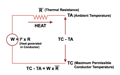
Figure 1
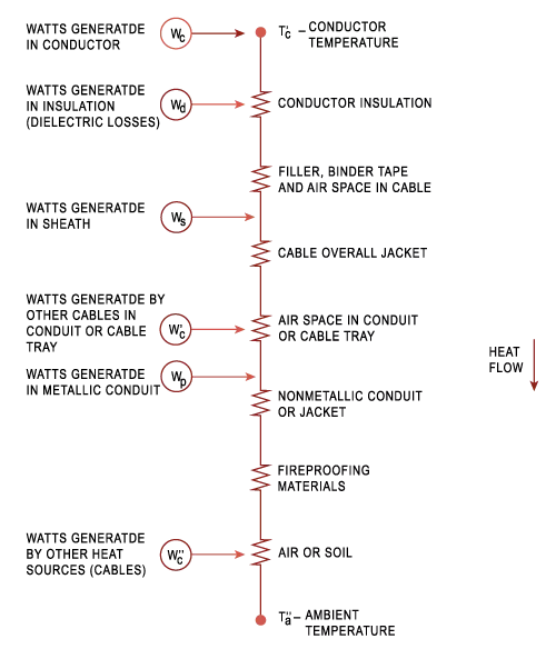
Figure 2
The above figure shows a series of thermal resistances through which heat flows from the heat sources in a cable system to ambient temperature.
Formula and Observation
Neher–McGrath method is the electrical industry standard for estimating cable ampacity, which is most frequently used by lookup in tables of precomputed results for typical configurations.
The equation in section 310-15(C) of the National Electrical Code, called the Neher–McGrath equation (NM) (given below), may be used to estimate the effective ampacity of a cable.
Where,
I = Ampacity (kA)
T C = Conductor temperature (Deg C)
Ta = Ambient Temperature (Deg C)
∆Td = Conductor temperature rise due to dielectric loss (Deg C)
Rdc = Conductor dc resistance (μΩ/ft)
YC = Loss due to conductor skin & proximity effects
Rca = Thermal resistance between conductor & ambience (Ω-ft)
∆Td compensates for heat generated in the jacket and insulation for higher voltages. It is insignificant for voltages below 2kV.
Term ( 1+YC ) is a multiplier used to convert direct current resistance (Rdc) to the effective alternating current resistance.
Observation of the ampacity equation shows how lower ampacities are inherent with the following:
- Lower conductor operating temperatures
- Higher soil ambient temperatures
- Smaller conductors (higher)
- Higher thermal resistivities of earth, concrete, insulation, duct, etc. (higher)
- Deeper burial depths (higher)
- Closer cable spacing (higher)
- Cables located in inner, rather than outer, ducts (higher)
Adequacy Of NEC Tables For Ampacity Calculations
For most installations, the ampacity tables in the NEC are adequate. Engineers, installers, and inspectors may need to use one of the many software programs available to make actual NM (Neher–McGrath) calculations in some situations where the use of the ampacity tables, including the safety margins, is insufficient.
For instance, in NEC tables, a soil temperature of 20° C at a depth of 36 inches and thermal resistivity of 90 K cm/W is considered. But this narrow range of conditions is not always applicable. What happens if there are several inches of polyurethane foam around a conduit? Yet, the addition of excessive thermal insulation will affect the ampacity of a conductor. And the southern US states often reach a soil temperature of 25° C at a depth of 36 inches reducing the ampacity by 5% or more.
Through the utilization of the Neher McGrath method, power systems engineers can construct a model of irregular setups, leading to a decreased discrepancy between the determined and actual ampacity.
How is the Neher McGrath Study conducted?
In order to perform the Neher-McGrath study, the following inputs are required:
Cable System Layout: Provide the layout of the cable system, including the arrangement and configuration of cables, cable lengths, and connections between cables.
Electrical Load Data: Specify the electrical load data for the cable system, such as the current magnitude and duration, power factor, and any variations in load over time. This information is crucial for determining the thermal behavior of the cables.
Cable Specifications: Provide detailed information about the cables in the system, including the type of cable (e.g., XLPE, PILC), conductor material, insulation type, conductor size, and any additional protective layers or features. The cable specifications will impact the thermal and electrical characteristics of the cables.
Ambient Conditions: Specify the ambient conditions surrounding the cable system, including the ambient temperatures, wind speed, and soil or air temperature gradients. These conditions affect the heat dissipation and temperature rise of the cables.
Grounding Configuration: Describe the grounding configuration used in the cable system, such as the type of grounding (e.g., solidly grounded, ungrounded), grounding resistors or reactors, and any additional grounding measures implemented.
Cable Installation Details: Provide information about the cable installation method, such as direct burial, duct installation, or overhead installation. This information helps assess the cable's heat dissipation and heat transfer characteristics.
System Fault Data: If available, provide information about fault currents, fault durations, and fault clearing times. This data is essential for evaluating the cable's short-circuit performance and determining its ability to withstand fault conditions.
We recently published a blog on Fault Analysis in Power Systems. Checked it out to grasp the information available in this blog.
The Neher-McGrath calculation is typically performed using computer software, such as ETAP which can quickly and accurately process the required inputs and provide the resulting temperature rise. However, manual calculations can also be performed using specialized tables and equations.
Let’s take a closer look at each of these steps ETAP 19.0.1 software.
Neher McGrath’s Study using ETAP 19.0.1
-
First of all switch to the underground raceway systems by clicking the fifth option (callout A) on the system bar.
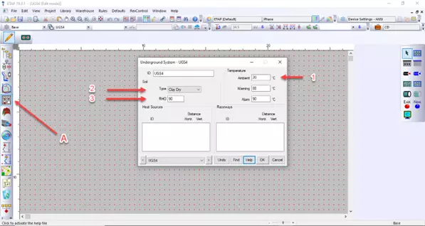
The 1st step is to input the soil information by double clicking on soil (grayed part with red dots) as follows:

Figure 1
Referring to call outs in figure 1:
Callout 1: Fill in the average soil ambient temperature at your location.
Callout 2: Fill in the type of soil in which your cable is buried into.
Callout 3: Enter the thermal resistivity of the earth (soil) in degrees C-cm/Watt.
-
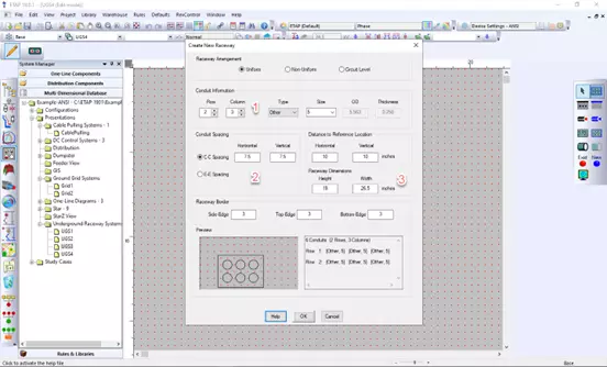
The 2 nd step is to fill the raceway details by clicking on new raceway tab on Edit toolbar.
Figure 2
The steps shown here are for uniform conduit.
Referring to callouts in figure 2:
Callout 1: Fill in the conduit information i.e., no. of rows & columns, type of material and its trade size (diameter of conduit in inches or centimeters).
Callout 2: Fill in the conduit spacing.
C-C: Center to center spacing.
E-E: Edge to Edge spacing.
Callout 3: Enter the raceway dimensions and depth (vertical distance to reference location).
-
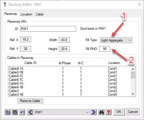
The 3 rd step is to enter the fill details by double clicking on the raceway.
Figure 3
Referring to callouts in figure 3:
Callout 1:Select the type of fill material in raceway. (Light aggregate and heavy aggregate are options for duct bank raceways, and Average Dry, Average Wet, Sandy Dry, Sandy Wet, Clay Dry, and Clay Wet are options for direct buried raceways.)
Note that the selection of fill material will not affect the value of RHO (thermal resistivity) .
Callout 2: Enter the value of thermal resistance of fill material in degrees C-cm/Watt.
-
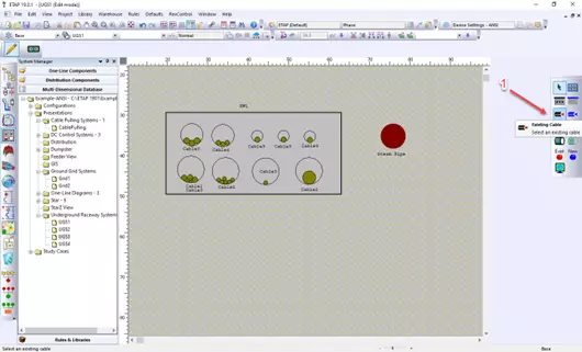
The 4 th step is to put the existing cables in conduit using the edit tool bar as shown in figure 4.
Figure 4
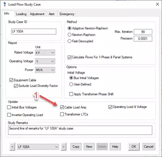
Then you need to update the operating load current of the cables by load flow study. For this go to edit study case in load flow mode and check mark the option that is shown by callout 1 in figure 5.
Figure 5
-
After performing load flow study, the operating current of cables will be automatically updated.
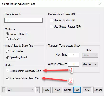
Now in UGS Study mode go to edit study case (red suitcase) and check mark these two options shown in figure no 6 as callouts 1 and 2.
Figure 6
-
Next step is to perform uniform ampacity calculation. This increases the loading of all raceway cables until the temperature of hottest cable reaches the maximum allowed limit.
This step can be shown in figure no 7 & 8.
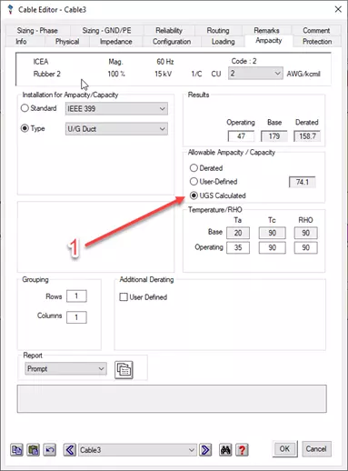
Figure 7
Referring to callout in figure no 7:
Callout 1: Checkmark this option, it will update the allowable ampacity of cable after running the ampacity calculation.
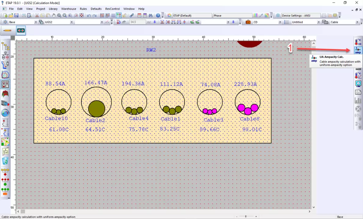
Now click the option shown in figure no 8 as callout 1. It will run the uniform ampacity calculation that will show you the allowable ampacity of cables until the hottest cable reaches its maximum allowed temperature.
Figure 8
Applications of the Neher-McGrath Calculation
The Neher-McGrath calculation is used in a variety of applications related to electrical power systems. Some of the main uses of this calculation include:
- Ensuring that electrical conductors are operated within safe temperature limits: The Neher-McGrath calculation is used to determine the maximum allowable temperature rise for electrical conductors, based on the conductor material and the type of insulation. This helps to prevent overheating and potential failure of the conductors.
- Optimizing the design of electrical systems: The Neher-McGrath calculation can be used to select conductor sizes and materials that will provide the desired level of performance while minimizing temperature rise and energy loss. This is important for maximizing the efficiency and reliability of electrical systems.
- Evaluating the impact of changes to electrical systems: The Neher-McGrath calculation can be used to analyze the potential impact of changes to an electrical system, such as adding or removing load, changing the conductor size or material, or modifying the insulation. This helps to ensure that the system remains safe and efficient after any changes are made.
- Troubleshooting electrical issues: The Neher-McGrath calculation can be used to help diagnose and resolve problems with electrical systems, such as overheating or failures. By analyzing the temperature rise of conductors, it may be possible to identify the cause of the issue and develop a solution.
In conclusion, the Neher McGrath study has proven to be an invaluable tool in the field of electrical engineering and plays a crucial role in ensuring the safety and reliability of electrical systems. This comprehensive study, which considers various factors such as heat generation, heat transfer, and thermal management, provides engineers with the necessary insights to design efficient and durable electrical systems.
We recently published a blog on Electrical Safety Program - Why Your Company Needs an Electrical Safety Program. Checked it out to grasp the information available in this blog.
At AllumiaX, we understand the significance of the Neher McGrath study and its implications for the success of your projects. As a leading service provider in the field, we are dedicated to helping you harness the power of this study and apply it effectively to your electrical system designs.
By partnering with us, you can benefit from our comprehensive range of services, which include conducting Neher McGrath calculations, providing detailed reports and recommendations, and offering practical solutions to optimize your electrical systems. Whether you are working on a small-scale project or a large-scale industrial installation, we have the knowledge and resources to support you every step of the way.
Don't compromise on the safety and efficiency of your electrical systems. Trust the experts at AllumiaX to guide you through the intricacies of the Neher McGrath study and ensure the optimal performance of your projects.
Contact us today to discuss your requirements and let us help you achieve electrical system designs that are reliable, cost-effective, and compliant with industry standards. Together, we can pave the way for a safer and more efficient electrical future.
AllumiaX is a licensed Engineering company headquartered in Seattle, Washington USA. We work with sub-contractors to deliver various Power System Engineering studies including DC arc flash, DC short circuit, and more. Get in touch with us or Request a Quote.


Abdur Rehman, PE
Author
Abdur Rehman is a professional electrical engineer with more than eight years of experience working with equipment from 208V to 115kV in both the Utility and Industrial & Commercial space. He has a particular focus on Power Systems Protection & Engineering Studies....
He earned his BSEE & MSEE from Washington State University in 2013 & 2017 respectively and an Engineering Technology Management degree in 2021.
Abdur Rehman is the CEO and co-founder of allumiax.com and creator of GeneralPAC by AllumiaX. He has been actively involved in various roles in the IEEE Seattle Section, IEEE PES Seattle, IEEE Region 6, and IEEE MGA.
Abdur Rehman is a board member of CordobaAcademy.org and enjoys local community volunteering. All AllumiaX blogs are special because of his love to share knowledge in the most intuitive way possible.
Stay Sharp & Join our Mailing List!
Subscribe to Allumiax Blog for updates on power system studies, tips, guides and insights on electrical engineering from industry leaders.

Recent Posts

Stay Sharp & Join our Mailing List!
Subscribe to Allumiax Blog for updates on power system studies, tips, guides and insights on electrical engineering from industry leaders.