Ferranti Effect in Transmission Line
In the vast system of electrical energy transmission there are many devices and components that are used to ensure safety of human life and devices, reliability, and efficient transmission of electricity. On the contrary, we see many losses and factors that decrease the efficiency of the system for which we take many precautions. One of such factors is the Ferranti Effect in the transmission line, which causes the receiving end voltage to be increased.
Would this condition of increased voltage be beneficial to our system and load or it is harmful for the system? Unfortunately, the effect this phenomenon has on our loading in not the one we want, creating a need for our system to be protected from this effect.
What is Ferranti Effect?

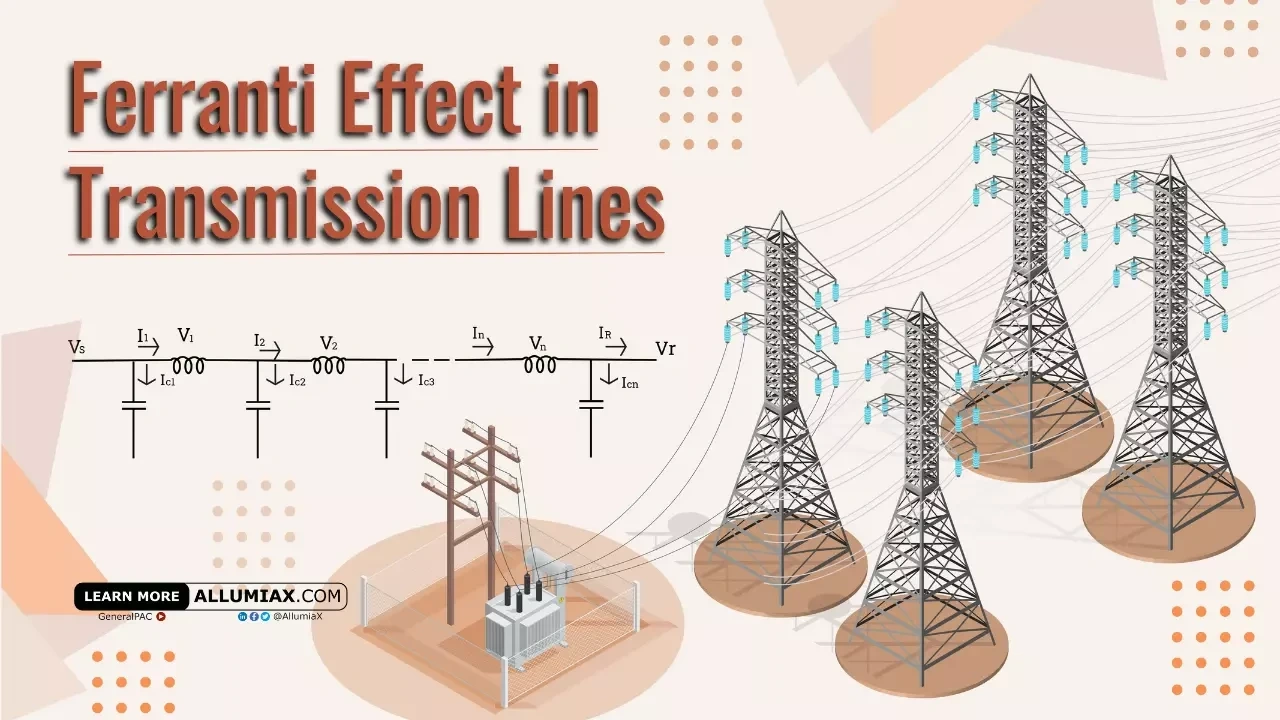
The above model shows the components of a transmission line. In this model we can see a voltage source followed by inductors, capacitors, and resistors. These components represent the line parameters as every conductor offers some resistance to the current, either due to its own resistivity or the magnetic field of current. Then in the end of this transmission line there is receiving terminal to receive power. This model will help us in understanding the Ferranti effect and the phasor diagram representing Ferranti effect. In the following phasor diagram different voltage drops adds up to a resultant of source voltage.
VS: Source Voltage
VR: Received Voltage
IC: Charging current
ICX: Voltage drop on Inductor
ICR: Voltage drop on Resistor

It is clear from the phasor diagram above that adding all the voltage drops across the line (ICR and ICX) and the receiving end voltage (VR) gives us a resultant equal to source voltage (). Normally this resultant should be greater than the receiving end voltage due to line losses, but in case of Ferranti effect this resultant is less than the receiving end voltage. The reason behind this fall in voltage would be discussed ahead in this blog.
Why does Ferranti Effect happen?
As discussed above there are some parameters in transmission line which effect the flow of current. One such factor is capacitance which is present due to the proximity of conductors. This capacitance gives rise to a charging current which flows in the transmission line. As charging current also flows in the transmission line along with load current, an increase in charging current would decrease the available capacity for the load current to flow. This would lead to the condition given below which needs to be fulfilled for the occurrence of Ferranti effect.
"The charging current should be greater than the load current"
Two factors which can cause the Ferranti effect are as follows:
- Line capacitance and charging current associated with it
- Loading present at the receiving end
| Capacitance | Greater capacitance leads to greater charging current, causing less load current |
| Loading |
Less loading ➡Low load current No loading ➡ No-load current The current present ➡ Charging current |
Going through the above Information, we can now understand the mechanism of the increase in Load end voltage.
How does Ferranti Effect occur?
Ferranti effect occurs when the charging current drawn by the line capacitances is greater than the load current in case of a lightly or no-loaded line.
Since conductors are present near each other in case of overhead as well as the underground lines, a capacitance is developed in the conductors. This capacitance is uniformly divided over the whole length of the conductor drawing a charging current which circulates in the system.
In case when the receiving end has no load or less load, the load current flowing in the system is either very low or zero and it would be inductive in nature. The charging current flowing in the circuit is due to capacitance and is leading in nature. In case of Ferranti effect, the current flowing in the system would mainly be charging current. This charging current would flow through the inductor, causing a voltage drop. This voltage drop would be proportional to the amount of current. As the charging current is very high due to the high capacitance of line, the voltage drop that appears on an inductor is also high.

The voltage drops mentioned above are shown in this figure. To avoid complications, voltage drop on resistors is not mentioned.

Here
VR = VS + V1 + V2 + V3 +........+ VN
IC = IC1 + IC2 + IC3 +........+ ICN
The voltage at each node is in phase with the voltage of source, so along the length of the line voltages can add up (because voltages present in series add up) resulting in a voltage at the receiving end which is greater than the sending end voltage (Only the current of capacitor and inductor varies in phase as in both cases the current and voltage are at a difference of 90o phase angle). The given phasor diagram also represents how the voltage drops adds up to give a greater voltage at receiving end.
Where does Ferranti Effect occur?
After getting to know about what Ferranti effect is and how it works, we need to know about the possible areas in which Ferranti effect can occur.
The table below shows us the types of transmission lines and underground cable where the Ferranti effect can be observed along with the reason of its occurrence.
| Transmission Line Length | Type | Nature | Ferranti Effect | Why |
|---|---|---|---|---|
| Short Transmission line | Overhead | Resistive and Inductive | No | As the capacitance of short transmission lines is negligible, so is the charging current resulting in no Ferranti effect |
| Medium Transmission line | Overhead | Resistive, Inductive, and Capacitive | Yes (for lines greater than 200 km) | For lines greater than 200 km, the capacitance value is high, resulting in charging current causing Ferranti effect |
| Long Transmission line | Overhead | Resistive, Inductive, and Capacitive | Yes | Capacitance is very high causing high charging current which reaches the limit of Ferranti effect |
| Multicore Cables | Underground | Resistive, Inductive, and Capacitive | Yes | As the conductors are present close to each other as compare to overhead lines, the value of capacitance fulfills the requirement of Ferranti effect |
Advantages & Disadvantages of Ferranti Effect
Advantages
- As discussed above, the charging current is leading in nature while the load current is lagging in nature. As both are opposite to each other, they would cancel each other’s effect, this would decrease the resultant current magnitude.
This phasor diagram shows that how the net current value is decreased if both inductive and capacitive currents are present in the system. In case of Ferranti effect, major contribution in net current would be of charging or capacitive current, resulting in a net current that is more inclined towards IC. The phase of net current depends on the difference between charging and inductive current magnitudes.

- As stated above, the load current is also low.

Considering both these conditions we conclude that the Ferranti effect is beneficial for us in following ways:
Less copper losses due to less load current
As the charging current increases, it causes a decrease in resultant current present in the cable. This can be observed from the phasor diagram shown above. This decrease in current decreases the copper losses, as:
Copper Losses = I2R
Improvement in power factor
The resultant current decreases because the charging current balances the effect of inductive current. Due to this there is more contribution of resistive current. An increase in contribution of resistive current also contributes to the improvement of power factor. This can be observed in the phasor diagram shown below.

This phasor diagram shows power factor improvement. An important thing to note here is that the improvement in power factor would be due to the angle between load current in normal condition and net current in case of Ferranti effect.
Efficient power transfer from sending end to receiving end
As the Ferranti effect contributes to decreasing copper losses and improves the power factor. These two factors help us in the efficient transfer of power from source side to the consumer side.
Disadvantages
Load can be damaged
Every load is designed for a certain current value which flows in it at the rated voltage. Exceeding that limit would harm the load. According to ohm’s law.
V = IR
If the voltage increases at constant resistance, the current present in the load would also increase. This will cause temperature rise in load and as a result the load would be damaged.
Decreased Ampacity
The transmission lines also experience the same thing, each cable has ampacity criteria which defines the allowable magnitude of current flowing through the cable.
Ampacity = Load Current + Charging Current
Greater charging current would cause decrease in the allowable load current.
Rectification of Ferranti Effect
Some precautions must be taken against Ferranti effect which are as follows:
-
Shunt Reactor
Charging current is reactive in nature. Increased charging current increases the reactive power present in the system. But due to less load present at the receiving end, it absorbs less reactive power from the system. This causes voltage instability in the system. Therefore, we need to absorb the access reactive power present in the system.
This excess reactive power is removed from the transmission lines by using shunt reactors at load end. The use of shunt reactors ` stabilize the system. Placement of shunt reactors depends on the length of the transmission line. The table below explains where shunt reactors are placed according to the type of transmission line.
Transmission Line Placement Medium Transmission Lines At receiving end Long Transmission Lines - At receiving end
- In middle of Transmission line
- At periodic intervals of about 250 to 300 km in case of very long transmission lines
Underground Cables At periodic intervals of about 15 to 20 km
-
Load Management
Another thing which could be done to reduce the occurrence of Ferranti effect is load management. Load management here means that the load present on the transmission line should fulfill the given condition.
Load Current > Charging Current
Let us say we have two transmission lines; both are loaded with low loads. This low load condition would lead to Ferranti effect. Ferranti effect would damage our system as mentioned in the disadvantages of Ferranti effect. But what if we shift both low loads to a single transmission line? That single transmission line would now have a load that will not satisfy the above-mentioned condition and the system would be protected.
Concluding this blog, we can say that Ferranti effect is beneficial for the transmission lines in some ways. But we cannot ignore this phenomenon as there are many disadvantages which need to be considered for efficient analysis of transmission lines. There are some techniques which can be applied to overcome Ferranti effect and in this way performance of transmission lines can be improved.


Abdur Rehman, PE
Author
Abdur Rehman is a professional electrical engineer with more than eight years of experience working with equipment from 208V to 115kV in both the Utility and Industrial & Commercial space. He has a particular focus on Power Systems Protection & Engineering Studies....
He earned his BSEE & MSEE from Washington State University in 2013 & 2017 respectively and an Engineering Technology Management degree in 2021.
Abdur Rehman is the CEO and co-founder of allumiax.com and creator of GeneralPAC by AllumiaX. He has been actively involved in various roles in the IEEE Seattle Section, IEEE PES Seattle, IEEE Region 6, and IEEE MGA.
Abdur Rehman is a board member of CordobaAcademy.org and enjoys local community volunteering. All AllumiaX blogs are special because of his love to share knowledge in the most intuitive way possible.
Stay Sharp & Join our Mailing List!
Subscribe to Allumiax Blog for updates on power system studies, tips, guides and insights on electrical engineering from industry leaders.

Recent Posts

Stay Sharp & Join our Mailing List!
Subscribe to Allumiax Blog for updates on power system studies, tips, guides and insights on electrical engineering from industry leaders.