Application of Synchronous Condensers in Industries
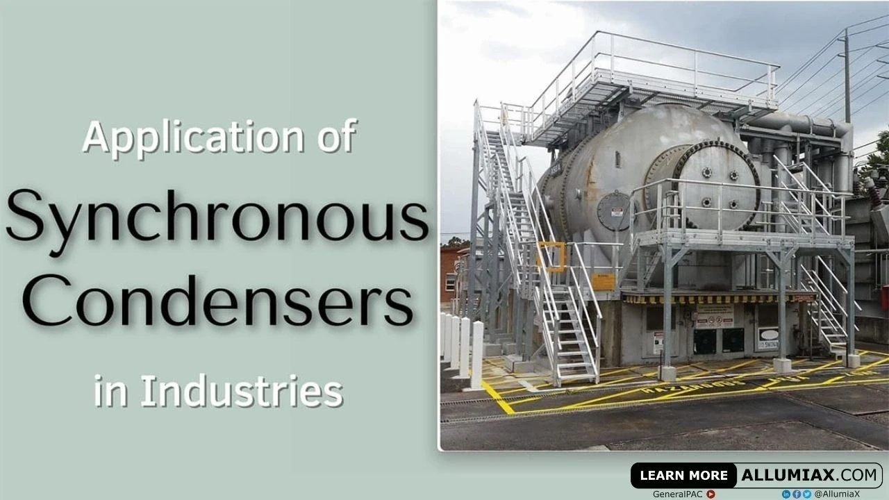
Synchronous Condenser Image By Mriya - Self-photographed, CC BY-SA 3.0, Link
A synchronous condenser is a synchronous motor running at no load and in over-excited mode. A synchronous motor in over-excited mode behaves as a capacitor which is indicated by a leading current or supply of VARs in the circuit by a synchronous motor.
Working Principle of a Synchronous Condenser:
As synchronous condenser is a synchronous motor so its principle of working will be as same as principles of synchronous motor. A synchronous motor works on the principle of motional EMF that is, a conductor tends to rotate due to the effect of the magnetic field. To provide a magnetic field, two ways are used that is a three-phase AC supply and a constant DC power supply to the stator.
The purpose of providing two ways of excitation is that it can rotate at synchronous speed as the synchronous motor works on the interlocking of the magnetic field produced due to the stator and dc field winding.
Changing the DC field excitation which may result in three possible outcomes, which are given as follows:
- On increasing dc supply initially, the armature current decreases which show that the stator is using less current for producing flux. It also shows that the motor is drawing less reactive (lagging) current. This is called under-excited mode.
- On further increase in dc field excitation, a point comes where the armature current is the least and the motor is said to be working at unity power factor. All the field excitation requirements are met through dc source (no field from stator ends required). This mode is called the normal-excited mode of synchronous motor.
- On the further increase of the field current through dc supply, the flux overly increases, and to counterbalance it, the stator starts supplying reactive power instead of absorbing it. As a result, the motor will draw a leading current.

Applications of Synchronous Condenser in Power Systems:
Due to the advantage of adjusting the VARS (reactive power) of a synchronous motor by changing the field excitation, the synchronous motor can be used for many applications of which some are as mentioned below
Power Factor Correction:
The power factor is the ratio of actual power consumed over total power supplied. It is given as:
For example, every motor requires some magnetizing current for the induction purpose (stator 3 phase voltage producing a rotating magnetic field and tend to induce a voltage in the rotor) due to which not all the power that is supplied is converted into useful work in motors, some power is used for the magnetizing purpose which is known as reactive power (Q).
In many industries, there is an induction motor that runs as a lagging load. It is being a concern to have a higher power factor which means that any lagging load should have as much as possible less magnetizing current due to the reason it does not do any useful work, only it is required for inducing EMF within a circuit.
Considering an example that a motor of 500KW is running at 0.8 pf lagging, considering that the voltage remains constant the current required for the magnetizing purpose(I*sinθ) will be quite lower than the current required for doing useful work (I*cosθ). Now if for the same motor power factor becomes 0.5, now more current would be required from the supply end, the overall reactive power is much more than required. In short, having a power factor causes a waste of electricity, that's why utility causes a penalty on having a low power factor.
Fig: effect of changes in power factor
To maintain a good power factor capacitor banks are used which provides the required current for the lagging load, thus reducing the current requirement from the supply end. In simple a capacitor bank as a leading load just cancels out the effect of lagging load, reducing stress from supply end to provide current.
Static capacitor banks are not preferable for the places where loads vary too much due to the reason that a varying load causes variation in current requirement and as the current varies with respect to a static capacitor then problem-related to overcompensation or under-compensation of power factor can be observed.
For example, two 500 KW motors are having a power factor compensation of 0.9 through a static capacitor of 3.12*10^-6. We can consider two cases here:
- Overcompensating: One of the motors is not used for some instant, then there will be an overcompensation of power factor for the single running motor. An overcompensation causes thermal insulation to be damaged, as overcompensation causes a large amount of current to flow through the motor (as capacitor compensates lagging current, overcompensation through capacitor causes I*cosθ to increase which may increase the permissible allowed value of conductors for the flow of current), causes heat in conductors and insulation, and resulting as damage of insulation.
- Undercompensating: Another cause could be that another 500KW of the motor is connected with the present two motors. Now there will be an under-compensation through the capacitor bank. A new capacitor bank installation would be required.
In short static capacitor bank installation would not be a good idea for power factor correction purposes. For this purpose, the synchronous condenser will be a better option as a synchronous condenser can have a varying compensation option by changing the field current. For example: if we require compensation for two 500 KW motors then changing field current of the synchronous motor according to the given load would result in the required power factor. if one of the motors stops then decreasing the field current would result in less leading current from the synchronous condenser and the required power factor would be achieved.
Mostly in transmission lines synchronous condenser is used for the power factor correction. For this purpose, controllers can be used which senses the overall VARs requirement and excitation of synchronous condenser changes proportionally.
VAR Compensator:
In a power system, short circuit faults produce a severe effect which includes blackout, other equipment useful life becomes less, and also stability issues may occur if not properly countered.
Short circuit refers to the unintentional connection between two conductors having different potential differences (having different magnitude or phase angles) which results in a heavy flow of current and also a voltage depression may also occur at that place.
A voltage depression at any point in the system can be counter by providing (reactive power) VARS at that point. For this purpose, a synchronous condenser can be used, as it can provide the required VARS by adjusting its excitation.
Inertia:
The loss of inertia refers to the problem which is usually encountered in the wind and solar system as there is a great fluctuation in frequency in this system as compared to the conventional system of producing electricity (fossil fuels, steam, gas, and hydro turbines). To counter it synchronous condensers with their spinning mass could solve it.
Limitations of a Synchronous Condenser:
- Not economical for less than 500KVAR compensation
- Noise and transient production
- Separate excitation required, increasing cost
- High maintenance cost
- There are significant losses in motors
- Cost of protective devices increases due to high Short Circuit Rating
Substitutes of Synchronous Condensers:
- Static VAR compensator (SVC)
- Static synchronous compensator (STATCOM)
- Series capacitor and reactors
- Shunt capacitors
- Transformer tapping
- FACT (Flexible AC Transmission) device
Comparison:
| Characteristics | Static VAR compensator(SVC | Synchronous condenser | Static compensator (STATCOM) |
|---|---|---|---|
| Mechanism | capacitors switching through thyristors for VAR compensation. | VAR compensation through changing field excitation | Uses electronically commutated circuits for the compensation purpose |
| Cost | As it has a stationary part only, the overall cost is much less. | The synchronous condenser has a high overall cost | It has a less overall cost |
| Maintenance | Less | High | Less |
| Power losses | Less | High | Less |
| Voltage degradation | SVC is dependent on the square of the voltage. It malfunctions on voltage depression | independent of voltage depression and are usually used for voltage compensation in short circuit | no capacitor, hence, no malfunction due to voltage degradation |
| Switching transient | Switching transient due to power electronics circuit | No switching transients | Switching transients due to power electronics circuit |


Abdur Rehman, PE
Author
Abdur Rehman is a professional electrical engineer with more than eight years of experience working with equipment from 208V to 115kV in both the Utility and Industrial & Commercial space. He has a particular focus on Power Systems Protection & Engineering Studies....
He earned his BSEE & MSEE from Washington State University in 2013 & 2017 respectively and an Engineering Technology Management degree in 2021.
Abdur Rehman is the CEO and co-founder of allumiax.com and creator of GeneralPAC by AllumiaX. He has been actively involved in various roles in the IEEE Seattle Section, IEEE PES Seattle, IEEE Region 6, and IEEE MGA.
Abdur Rehman is a board member of CordobaAcademy.org and enjoys local community volunteering. All AllumiaX blogs are special because of his love to share knowledge in the most intuitive way possible.
Stay Sharp & Join our Mailing List!
Subscribe to Allumiax Blog for updates on power system studies, tips, guides and insights on electrical engineering from industry leaders.

Recent Posts

Stay Sharp & Join our Mailing List!
Subscribe to Allumiax Blog for updates on power system studies, tips, guides and insights on electrical engineering from industry leaders.