Transfer Switches and Safety Switches
One of the most important concerns in an electrical power system is the continuous supply of power to the load. To maintain reliability, various facilities (for example, hospitals, schools, and industries) use different backup power sources (if the primary source (utility) is affected for any reason), that is why switches are used. Switches that are used in the facilities make it safe to close or transfer live circuits. In commercial and industrial facilities where high currents are involved, these switches are an essential component of the distribution system. By closing and opening circuits, they make the transfer of power easy and secure. In this blog we will be discussing about different types of switches (transfer and safety switches), importance, applications and comparison of these switches.
What is a Transfer Switch?
Transfer switches are used to let you safely transition power from the utility to your standby generator at times when the utility power source fails. This is particularly useful in facilities where continuous power is required, like hospitals, manufacturing facilities, data processing centers and a lot of other commercial and industrial units. Secondary source of power could be a generator or a back-up utility feed depending on the availability of a utility. They are very important for safety of circuits and personnel as they stop the mains power from coming in contact with the backup generator and also prevent back feeding from the generator to the utility risking the lives of unsuspecting electricians working on the grid. Have you installed the right transfer switch in your facility? At AllumiaX we offer Short Circuit and Arc Flash Analysis to check the safety and reliability of the equipment installed, Click here to contact our professional.
Operation of Transfer Switches
Manual Transfer Switches
These transfer switches need to be operated manually, by changing position of a lever mounted on the side of a transfer switch or by pushing a button. Manual transfer switches are robust as they don’t have any electronic parts so chances of them failing are slim.
They are a great option when a delay in switching power is not an issue as they are least expensive choice in the options available. They are not ideal for facilities where continuous uptime is a legal or operational requirement because this mode takes the maximum time for switching.
Non-Automatic Transfer Switches
The difference between a non-automatic and manual transfer switch is their function. A non-automatic transfer is manually initiated and electronically operated, it gives you the ease of operating the transfer switch when the operator presses the button placed on the switch, button can also be placed remotely when the transfer switch is difficult to reach or unsafe for a technician to access.
This increases safety for the technician operating the switch as well as shaving off downtime during transitions because switching is done electromechanically.
Automatic Transfer Switches
Automatic transfer switches don’t need a person to activate switching, they have a smart controller which decides when to initiate and operate the transfer between the sources present to feed the load. For example, when a power plant for a college campus fails to produce power, an ATS (Automatic Transfer Switch) will detect this power loss automatically and will initiate and operate the mechanism to transfer the source of power from the power plant of the college campus to the utility feed without the need of a person to oversee the operation. Also, automatic transfer switches are used for safety-critical operations when it is necessary to switch power quickly. ATS tend to be more expensive than all the other switches, but they eliminate the need of an operator.

Transfer Switch Transitions
Open Transition

This transfer mechanism is a ‘break before make’ mechanism, such that the load is disconnected first before shifting the source of power. Open transitions could be open-delayed or open in-phase transition. A fixed delay is set in between transitions in open delayed; this is when a delay is allowable. A residential circuit would be a good fit for open delayed as a delay window of a few seconds is allowable.
The transfer switch shifts to the load once the phase, voltage and frequency of the new source synchronizes with the previous power source in open in-phase transition. This transition is controlled by a digital-micro controller with a few milliseconds delay (normally 150 milliseconds or less). Such a transition is preferred where inductive loads have a considerable share of the total load, for example in a shopping mall where elevators and air conditioning take up a large amount of the total load.
Closed Transition

This type of transfer is preferred when even a brief interruption of power is not acceptable like in a textile dying plant where outage of power for even a few seconds will cause the whole batch to be colored the wrong shade, or in a hospital where power outage will mean loss of human life.
These transfer switches use make-before-break transition which lasts less than 100 milliseconds. It is usually 2 to 3 cycles so there is no time delay between opening of the first switch and closing of the second switch, making the transition smooth. The conditions that are checked by the ATS in Closed transition systems are as follows:
- Phase, voltage and frequency of both sources should be synchronized at the time the switch “parallels” both sources, if phase difference is greater than 10 degrees then the system may not be able to handle the amount of surge current caused by the phase difference, harming the components in the circuit (damaging cables, tripping breakers).
- IEEE 1547 allows generator sets or systems of paralleled generator sets between 1.5 and 10 MVA to be up to 10 deg out of phase with the utility when closing to the grid, with higher phase difference limits for smaller systems.
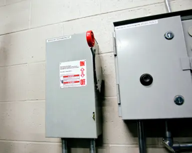
Why do we need Safety Switches?
Safety Switches are a requirement by the NEC (National Electric Code) in all commercial and industrial applications. According to article 430.102B of the NEC a safety switch must be in sight of motors and all manufacturing equipment. In sight means less than 50 feet from the equipment. Safety switches can be used at service entrances as well, which means that they can be used to cut-off power from the utility to the whole facility.
How does a Safety Switch work?
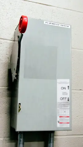
A safety switch or a disconnect switch is a device that constantly monitors current and detects fault current in the system, it is essential for safety of people working near the electrical equipment. Upon finding a change in the circuit the safety switch will open the circuit instantly (no intentional delay).
One might confuse the working of a safety switch with a circuit breaker. In simple terms, a circuit breaker is a device that protects electrical equipment like lights, wiring and motors from overloading and shorting out which leads to over-heating, fire and damage to other parts of the system. On the other hand, a safety switch is installed to prevent an electrical shock to people while at work in some manufacturing facility or while using a baby monitor at home. The main difference between these two devices is that the circuit breaker (trip unit) is designed to protect equipment from higher currents than its circuits were designed for, while a safety switch was built to keep people safe when there is any leaking current available.
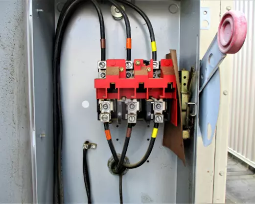
Fusible Safety Switches and Non-Fusible Safety Switches
Safety switches come in both fusible and non-fusible options, Fusible safety switches have an option to fit fuses in the safety switch, such safety switches provide a convenient means to manually open or close the circuits and provide circuit protection as well.

Non-fusible safety switches provide no such protection from overcurrent, they just offer the functionality to open and close the circuits, protection for the circuits must be provided by external overcurrent protection devices such as fuses or circuit breakers.

Types of Safety Switches
According to application, there are four types of safety switches:
- General duty safety switches
- Heavy duty safety switches
- Double door safety switches
- Elevator control safety switches
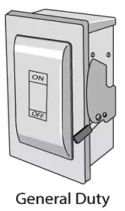
General Duty Safety Switches
General duty safety switches that are used in residential and commercial applications. They are suitable for light duty applications, generally facilities where loads are not more than 30-600 amps and Voltages not more than 240 V, they could be used for service entrance applications or light duty motor circuits.
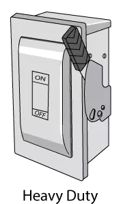
Heavy Duty Safety Switches
Heavy Duty safety switches are used in industrial and commercial applications where service continuity is critical, they have a current rating higher than light duty safety switches as the name suggests, their operating range extends from 30-1200 Amps and are suitable for applications up to 600 V.
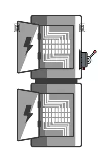
Double Door Safety Switch
These fusible heavy duty safety switches have compartments that offer isolation from the line side to the load side through the compartmentalized design and the internal barrier that separates the line side from the load side. Contact with line-side power can be fatal for operators, the insulation offered by a double door safety switch ensures safety for operators during maintenance. Operating ranges of double door safety switches are same as heavy duty safety switches that is 30-1200 Amps and up to 600 Volts.
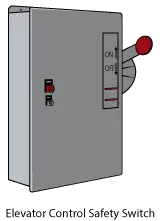
Elevator Control Safety Switch
This switch helps meet all the codes associated with fire protection and safety requirements in elevators. Elevator control safety switches are ready for quick installation decreasing the amount of time and labor required to put together all components required. Operating ranges of elevator control safety switches are 30-400 A and 208-600V.
Difference between Transfer Switches and Safety Switches
Transfer switches are mostly used for transferring loads from one power source to another. A load could be connected to a utility but upon power outage we can shift the power source from the utility to the generator.
Safety switches on the other hand are used to connect and disconnect the power source from loads (motors) and used as a disconnecting means for a service entrance. They open the circuit once they detect a change in it, this change in the circuit could be a person who got electrocuted, the safety switch will sense this change and trip in a few milliseconds saving the person from getting a fatal shock.
Comparison
|
Characteristics |
Transfer Switch Automatic |
Transfer Switch Manual |
Safety Switch Fusible |
Safety Switch Non-Fusible |
|
Objective |
Used to feed load from either of two sources or allows a supply to feed either one of the two loads. |
Used to feed load from either of two sources or allows a supply to feed either one of the two loads. |
Used to control circuits, protecting equipment and personnel. |
Used to control circuits, protecting equipment and personnel. |
|
Fused |
Very Uncommon to be fused. |
Very Uncommon to be fused. |
Space Available for adding fuses. |
Space not available for adding any fuses. |
|
Operation |
Has the option to be controlled remotely. |
Cannot be controlled remotely. |
Manually operated. |
Manually operated. |
|
Price |
Higher than Manual Transfer Switch. |
Comparatively lower than Automatic transfer switch. |
Higher than Non-Fusible Safety Switch. |
Comparatively lower than Fusible Safety Switch. |
|
Maintenance |
Annually |
Annually |
Changed after every time the fuse is burned or quarterly. |
Quarterly |
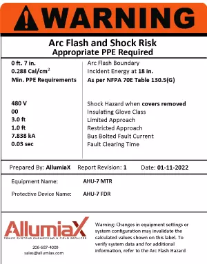
We at Allumiax access all safety hazards related to electrical equipment in all industrial and commercial facilities. We can check if the safety switches and transfer switches used in your facility are of the appropriate rating and if they meet all standards or not. Click here to learn more about the Short Circuit current rating of Safety switches and other equipment in our Short circuit study article. After testing the equipment we include Arc Flash Labels as attached below in our reports in compliance with NFPA 70E. These labels help Electricians working on the equipment know what level of safety gear to wear.
Get in touch with us here to check that the ATS,MTS and safety switches used in your facility are adequately rated according to the short circuit current available and normal operating ranges of your facility.


Abdur Rehman, PE
Author
Abdur Rehman is a professional electrical engineer with more than eight years of experience working with equipment from 208V to 115kV in both the Utility and Industrial & Commercial space. He has a particular focus on Power Systems Protection & Engineering Studies....
He earned his BSEE & MSEE from Washington State University in 2013 & 2017 respectively and an Engineering Technology Management degree in 2021.
Abdur Rehman is the CEO and co-founder of allumiax.com and creator of GeneralPAC by AllumiaX. He has been actively involved in various roles in the IEEE Seattle Section, IEEE PES Seattle, IEEE Region 6, and IEEE MGA.
Abdur Rehman is a board member of CordobaAcademy.org and enjoys local community volunteering. All AllumiaX blogs are special because of his love to share knowledge in the most intuitive way possible.
Stay Sharp & Join our Mailing List!
Subscribe to Allumiax Blog for updates on power system studies, tips, guides and insights on electrical engineering from industry leaders.

Recent Posts

Stay Sharp & Join our Mailing List!
Subscribe to Allumiax Blog for updates on power system studies, tips, guides and insights on electrical engineering from industry leaders.