Relay Settings in Real Power System: Requirements And Consideration

This blog consists of a discussion on the parameters and rules in the relay setting and how they are implemented.
The power system consists of generators, transformers, transmission lines, and other equipment whose costs is in millions of dollars. Power system equipment can severely be affected by faults, reducing their lifespan, or even getting burst or damaged which also reduces reliability and increases utility costs.
Power protection devices can be used to protect power systems equipment from getting damaged due to heavy faults and surges. Protective devices ensure the reliable operation of the system by sensing faults, surges, or any abnormal condition and according to the severity takes the right decision at the right time.
To configure protective devices such as making a relay setting, having all the consideration of the fault severity and decision-making time, it is important to know parameters, rules, and protection zone so that the reliability of the power system having continuous supply, is not compromised. Without prior knowledge of relay settings, reliability is affected badly and it can cause a penalty to the distributor.
Types of Relay
Based on Operating Mechanism:
-
Electromagnetic (mechanical type)
-
Static (electronics type)/ Solid State Relay
-
Microprocessor-based (programmable and communicating type)
Based on Actuating Parameter:
- Overcurrent
- Under/over voltage
- Impedance
- Under/over frequency
Based on Application:
- Primary
- Backup
Based on Protection Scheme:
- Differential protection (difference in current)
- Distance protection (V/I and time + distance)
- Directional protection (time + direction of current)
- Reverse power relay (negative sequence component)
Overcurrent Relay
Overcurrent is the most used relay protective scheme as compared to others.
Definition:
An overcurrent relay works on sensing current. It operates whenever the current exceeds a permissible value or pickup value.
Layout:
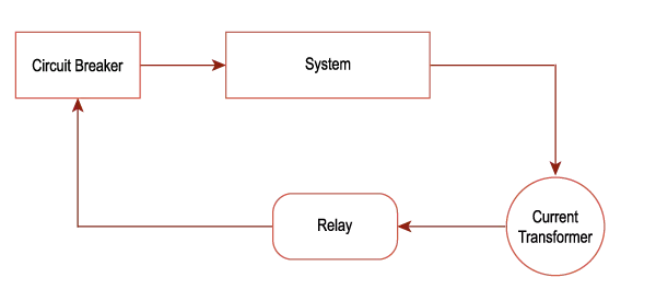
An overcurrent relay works such that the system current is sensed by a current transformer (C.T). The primary side of C.T is connected to the system and the secondary side with a relay. In case of:
- Fault/overload/ overcurrent: the relay operates and gives a trip signal to the breaker with respect to time.
- No fault: the relay performs no operation
Types:
| Instantaneous OCR |
Definite time OCR |
Inverse time OCR |
|---|---|---|
|
Trips after the current exceed the allowable range with negligible delay |
Trips after the current exceed the allowable range with a certain time delay |
Tripping time is inversely proportional to the magnitude of current |
Be cleared to avoid damage to the apparatus. Following inverse time characteristics have been standarized.
-
Inverse definite minimum time (IDMT) OC relay.
-
Very Inverse time OC relay.
-
Extremely inverse time OC relay
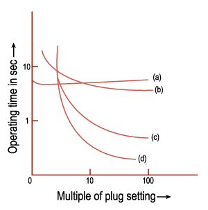
Characteristics of various over-current relays: (a) definite time, (b) IDMT, (c) very inverse, and (d) extremely inverse.
Common Terms
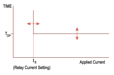
Pickup Current (Ipu):
Definition:
Minimum amount of current required for the operation of the relay.
Objective:
Power system components work properly at a certain allowed current and when the magnitude of current exceeds a certain value (as in case of a fault), it can cause damage to the component and the entire system reliability is compromised. The relays are designed to operate above these rated currents. The pickup current is thus set at the maximum allowed current.
Formula:
Ipu = Rated CT output * %current setting
where,
Rated CT output is the rated current at the secondary side of the current transformer, typically 1A or 5A.
Current Setting:
Definition:
To adjust the pickup current (Ipu) to the desired value.
Objective:
C.T output comes in standard for example: 5A according to IEC and 1A according to IEEE.
The current setting sets the pickup value according to it so that the relay can operate at pickup current instead of working at rated C.T output
Plug Setting Multiplier (PSM):
Definition:
The ratio of fault current in the relay coil and the pickup current.
Objective:
It defines the severity of a fault. According to the severity of the fault, the relay may decide the time of operation.
For example:
- if overcurrent occurs the P.S.M would be low, and tripping may take after some delay
- if a short circuit occurs then PSM would be high, and tripping would be instantaneous
Formula:
Time Setting Multiplier (TSM):
Definition:
A relay time of operation can be adjusted using a time setting multiplier. Gives the real time of operation (TOP) with respect to time/PSM curve
Objective:
Sometimes it is desired to trip the relay much earlier than the provided time from its time/PSM curve.
A dial is provided whose value ranges from 0 to 1, with step of 0.05, the dial is adjusted at the required value and multiplied with the relay operating time from time/PSM curve to obtain required time of operation
Formula:
top = TSM * time PSM curve time
Time/PSM Curve:
Definition:
Time/PSM curve represents graph between time (y-axis) and PSM (x-axis). It represents the time of operation of a relay according to PSM, when TSM is 1.
Objective:
The time/PSM curve helps in achieving the time of tripping according to the severity of overcurrent or fault. The manufacturer provides the relay time/PSM curve of a relay and it can be created/varied in microprocessor based relay.
Calculation of Relay Operation Time
Procedure:
- Step1: Calculating pickup-current.
- Step2: Converting fault current into relay coil current by dividing fault current with C.T ratio.
- Step3: Calculating PSM
- Step4: From the time/PSM curve of a provided relay, determine the value of time of operation (at TSM=1) from the calculated PSM.
- Step5: Multiplying the time from time/PSM curve with the required TSM to get the time of operation.
Solved Example:
Considering the following data:
C.T = 100 / 1
Breaker continuous current = 80 A
TSM = 50%
Fault current = 800 A
Time = 2s (at PSM=10 for time / PSM curve)
Solution:
Current setting = 80 / 100 (from eq2)
Current setting = 0.8 or 80%
Ipu = 1*0.8 (from eq 1)
Ipu = 0.8 A
Relay coil current = 800 / (100 / 1) (from eq 4)
Relay coil current = 8
PSM = 8 / 0.8 (from eq 3)
PSM = 10
top = 2 * 50 / 100 (from eq 5)
top = 1s
Principle of Time/Current Grading
A time/PSM curve for relays can be set in any of the three ways, which are described as:
-
Discrimination by Time:
A constant time setting is given to each relay irrespective of the magnitude of the current.
The issue with this method is that the relay closest to the source has the largest delay while it has the maximum fault current that could flow within the system, which can damage the system due to a large time delay.

-
Discrimination by Current:
This method is based on the phenomenon that fault current amplitude varies with a change in impedance between source and fault.
The main issue with this method is that there should be a good distance between two breakers as the relay would not be able to detect faults if the distance between two zones breaker is less.
-
Discrimination by both Time and Current:
This method is based on the fact that with an increase in fault current, the clearance time should reduce.
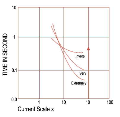
There are three types of inverse time-current characteristic curves:
- Inverse definite minimum time (standard inverse)
- Very inverse time
- Extremely inverse time
Extremely inverse time has the minimum clearance time with an increase in fault current than very inverse time and lastly inverse definite minimum time.
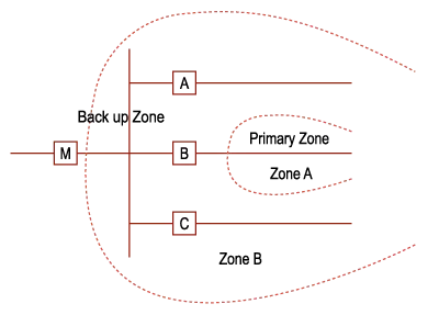
Primary and Backup Protection
Zones of Protection:
For better security of elements that is relay associated with faulty area sense and clear the fault on first priority power system components are divided into the region. Faults can be classified into two with respect to the defined zone:
- Internal fault: fault within the zone
- External fault: fault outside the zone
Reach point: The farthest point from a relay in a specified zone.
Reach of the relay: Distance between relay and reach point.

Here the power system zones are being overlapped due to reason that no zones remain unprotected.
As each power system element generator, transformer, transmission lines, and others have a different structure, cost, and functionality, they are divided into a separate zone for better security. As fault within a zone can be internal and external, depending upon the type of fault protection scheme can be classified into two types:
Primary Protection:
They are concerned with internal fault and are efficient enough to detect a fault in the least possible time within a zone and gives a trip signal. Primary protection schemes are usually implemented using differential, distance, and directional overcurrent protection.
Differential Protection:
Differential protection works on the current matching principle that is two CTs are connected in a region in such a way that whenever there is a difference in current within that region, the relay gives a trip signal, else no tripping.
They are used in power transformers, generators, and bus bar protection schemes.
Distance Protection:
In transmission lines, it is not possible to implement differential protection. For transmission line protection, distance protection is used which is based on ohm’s law that measures voltage and current, if the measured impedance is less than the transmission line impedance then the relay gives a trip signal.
Directional Overcurrent Protection:
A directional protection scheme becomes functional in the case of a double-end feed system or parallel lines or a ring main system, where a fault gets fed from both sides. It senses the current magnitude and direction for the decision-making purpose.
Backup Protection:
For better reliability purposes, backup protection schemes are used. They are less efficient than primary protection but are used for the purpose, if primary protection does not give a trip signal due to some reason in case of fault, the backup protection trips after some delay. They are also used in detecting external faults. Backup protection is achieved using overcurrent relay.
Coordination Methodology
The following methodology is adopted for the overcurrent protection of the power system:
Data Required:
-
Single line diagram, indicating rating, manufacturer, and types of each element including C.T, motors, generators, transformer, cables and protective devices (for accurate short circuit calculation and relay coordination)
-
Impedance of rotating machines and transformers (as they also take part in fault current)
-
Minimum and maximum fault current. (for time-setting purposes)
-
Maximum loading ( to get an overload of the system)
-
Voltage level (for selection of the type of circuit breaker and relay)
-
Starting and inrush current, damage curves of cables and transformer, induction motor stalling time and acceleration time (these variables are considered in order to prevent nuisance tripping)
Rules:
- If possible, relays having similarities in operation should be placed in series.
- Relay farthest from the source must have a current setting less than or equal to the relay behind it, as the relay in front requires less current to operate as compared to the relay behind it.
IEEE Standards for Relay Settings:
|
IEEE Std C37.91-2008 |
IEEE Guide for Protective Relay Applications to Power Transformers |
|
IEEE Std C37.95-2002 (R2007) |
IEEE Guide for Protective Relaying of Utility-Customer Interconnections |
|
IEEE Std C37.96-2012 |
IEEE Guide for AC Motor Protection |
|
IEEE Std C37.99-2012 |
IEEE Guide for the Protection of Shunt Capacitor Banks |
|
IEEE Std C37.101-2006 |
IEEE Guide for Generator Ground Protection |
|
IEEE Std C37.102-2006 |
IEEE Guide for AC Generator Protection |
|
IEEE Std C37.108-2002 (R2007) |
IEEE Guide for the Protection of Network Transformers |
|
IEEE Std C37.109-2006 |
IEEE Guide for the Protection of Shunt Reactors |
|
IEEE Std C37.110-2007 |
IEEE Guide for the Application of Current Transformers Used for Protective Relaying Purposes |
|
IEEE Std C37.112-1996 (R2007) |
IEEE Standard Inverse-Time Characteristic Equations for Overcurrent Relays |
|
IEEE Std C37.113-1999 (R2004) |
IEEE Guide for Protective Relay Applications to Transmission Lines |
|
IEEE Std C37.114-2004 |
IEEE Guide for Determining Fault Location in AC Transmission and Distribution Lines |
|
IEEE Std C37.117-2007 |
IEEE Guide for the Applications of Protective Relays used for Abnormal Frequency Load Shedding and Restoration |
|
IEEE Std C37.119-2005 |
IEEE Guide for Breaker Failure Protection of Power Circuit Breaker |
|
IEEE Std C37.234-2009 |
IEEE Guide for Protective Relay Applications to Power System Buses |
|
IEEE Std C57.12.59-2001 (R2006) |
IEEE Guide for Dry-Type Transformer Through-Fault Current Duration & Errata 2006 |
|
IEEE Std C57.109-1993 (R2008) |
IEEE Guide for Liquid-Immersed Transformer Through-Fault Current Duration |
|
IEEE Std 620-1996 |
IEEE Guide for the Presentation of Thermal Limit Curves for Squirrel Cage Induction Machines |
Coordination for Radial Feeders:
Following example shows the coordination of three relays A, B, and C.
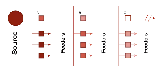
When a fault occurs in front of relay C, it will be sensed by all 3 relays. Here relay C will act as a primary relay and relay B and A as backup, it will be desired that relay C trips first, then relay B if relay C fails to trip, and then relay A if relay B fails to trip. Here time of operation of relay C is adjusted lowest among the two other relays for maximum and minimum fault front of relay C.
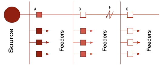
When a fault occurs in front of relay B and relay C, it will be sensed by only relay A and B relays. Here relay B will act as a primary relay and relay A as backup, it will be desired that relay B trips first, then relay A if relay B fails to trip. Here time of operation of relay B is minimum than relay A for maximum and minimum fault front of relay C.
Directional Overcurrent Relay Setting for Different Scenarios:
Following are the cases where directional overcurrent protection is used to fulfill the selectivity requirement.
Load Connected to a Generator through Parallel Transmission Line:
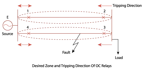
In the given system relay 1 & 4 are non-directional relay while 2 & 3 are directional relay with minimum TMS.
Ring System:
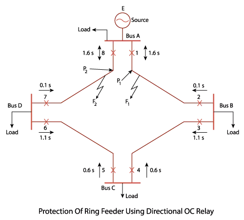
In the given system, 1 & 8 are non-directional relays while 3, 5 & 7 are relays that will sense fault in a clockwise direction, and 2, 4 & 6 in counter-clockwise direction that is 2, 3, 4, 5, 6, 7 are directional relays.
In this blog we have understood different types of relays, their settings, and their coordination methodology and in last we have included a brief overview regarding directional overcurrent relay for different types of systems. Relay settings are the essential part of protective scheme for Power System and its coordination is one of the prime focuses of protection for Power System.
We here at AllumiaX perform different types of studies related to the protection of Power system. Engineers at AllumiaX are capable of providing high quality protective device coordination study including Protective Relay Settings and Coordination Services. Get in touch with us at support@allumiax.com


Abdur Rehman, PE
Author
Abdur Rehman is a professional electrical engineer with more than eight years of experience working with equipment from 208V to 115kV in both the Utility and Industrial & Commercial space. He has a particular focus on Power Systems Protection & Engineering Studies....
He earned his BSEE & MSEE from Washington State University in 2013 & 2017 respectively and an Engineering Technology Management degree in 2021.
Abdur Rehman is the CEO and co-founder of allumiax.com and creator of GeneralPAC by AllumiaX. He has been actively involved in various roles in the IEEE Seattle Section, IEEE PES Seattle, IEEE Region 6, and IEEE MGA.
Abdur Rehman is a board member of CordobaAcademy.org and enjoys local community volunteering. All AllumiaX blogs are special because of his love to share knowledge in the most intuitive way possible.
Stay Sharp & Join our Mailing List!
Subscribe to Allumiax Blog for updates on power system studies, tips, guides and insights on electrical engineering from industry leaders.

Recent Posts

Stay Sharp & Join our Mailing List!
Subscribe to Allumiax Blog for updates on power system studies, tips, guides and insights on electrical engineering from industry leaders.