[NEC Guide] Importance of Achieving Selective Coordination for Critical Power Systems!

One of the most important parts of any facility is the electrical distribution system.
Nothing will stop all activity, halt production, cause inconvenience and possibly panic, more than a major power failure.
Selective coordination is critical for the reliability of the electrical distribution system.
What is Selective Coordination?
According to the NEC, selective coordination means that the fuse or circuit breaker closest to the fault opens up without opening up the fuse or the circuit breaker that feeds it (from the upstream side). So you won't have blackout conditions that can occur if there is a fault somewhere downstream.
Article 100 of the NEC defines this as:
Localization of an over-current condition to restrict outages to the circuit or equipment affected, accomplished by the choice of over-current protective devices and their ratings or settings.
Selective Coordination is actually mandated by the NEC for things like emergency systems, standby systems, elevator circuits, healthcare facilities and, as was added in 2005, critical operation power systems, which is for buildings that must operate during national emergencies.
NEC Selective Coordination is required for:
- Emergency systems (NEC 700.27)
- Standby systems (NEC 701.18)
- Elevator circuits (NEC 620.62)
- Healthcare facilities (NEC 517.26)
- Critical Operations Power Systems (NEC 708.54)
We had previously written an article about the importance of Arc Flash Hazard Analysis. If you haven't checked it out, please CLICK HERE. It will help you to grasp the information available in this article easily.
What would happen if you do not have Selective Coordination?
The figure below shows the difference between a system without selective coordination and a system with selective coordination.

If you had an arc flash or a short circuit that occurred downstream, and you did not have a selectively coordinated system, the fault would propagate up. It would open up the fuse or circuit breaker upstream, and eventually open up the main fuse feeding the whole building. So if you're not selectively coordinated, the whole building can face a blackout, and you would not be able to identify where the problem or fault is. This is a very difficult position for troubleshooting.
What happens if you have a Selectively Coordinated system?
In a selectively coordinated system, only the protective device immediately on the line side of an overcurrent opens. All other upstream protective devices remain closed.
If you have a fault occurring at some point, then just the fuse or circuit breaker that feeds that circuit will open up and will leave everything else operating. So you won't have a blackout condition, the rest of the building is up and running, and you can quickly identify the problem and fix it.
There are several other benefits of Selective Coordination. A Selectively Coordinated system:
- Aids in the continuous operation of critical circuits
- Reduces or eliminates blackouts
- Increases safety and reliability of the system
- Minimizes damage and downtime
- Increases productivity
- Speeds restoration pf faulted of faulted circuits
- Reduces arc-flash hazards
Methods of Performing a Selective Coordination Study
- For fuse systems, 600V or less, use the published selectivity ratios (presented in the next section). The ratios apply for all overcurrent conditions including overloads and short-circuit currents. Using the fuse selectivity ratio method is easy and quick. There is no need to use time-current curves.
- Computer programs allow the designer to select time-current curves published by manufacturers and place curves of all OCPDs of a circuit on one graph. However, simply plotting the curves does not ensure selective coordination. The curves must be analyzed and interpreted properly in relation to the available fault currents at various points in the system.
- Overlays of time-current curves, with the manufacturers' published data, are hand traced on log-log paper. Proper analysis and interpretation are important in this case, also.
Regardless of which method is used, a thorough understanding of the time-current characteristic curves of overcurrent protective devices is essential to provide a selectively coordinated system.
Fuse Coordination Table
For fuse systems, verification of selective coordination is quick and easy, merely adhere to fuse ampere rating ratios as indicated by the manufacturer.
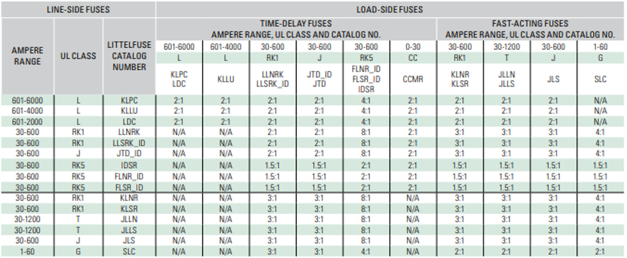
The chart above shows that if you are using a current limiting fuse, then as long as you maintain a certain ratio from the line side fuse (the fuse feeding the circuit) and the load side fuse (the circuit that the line side fuse is feeding), you are assured of selective coordination under any condition.
For example, if you had a 30amp fuse feeding an individual circuit, if you use an RK-1 fuse (30A), and an RK-1 fuse feeding it, then you have to maintain a ratio of 2:1.
However, if you were to change the load of the 30A fuse to an RK-5 fuse rather than an RK-1 fuse, then according to the chart, you now have to maintain an 8:1 ratio. In other words, the rating of the downstream fuse is required to be 8 times less than the upstream fuse.
Circuit Breaker Coordination Study

The ability of circuit breakers to achieve coordination depends upon the maximum available fault current at the overcurrent protective devices where selective coordination is required. This fault current can be calculated using several programs.
Once the maximum available fault current is determined, the design engineer must select the circuit breakers and verify that they are selectively coordinated up to the maximum available fault current.
This is a two-step process; the first is to plot the time-current curves and the second is to plot the maximum available fault current on these curves. There must be no overlap of curves at these available fault currents.
For those circuit breakers that clear faster than 0.1 seconds in the instantaneous region, the available fault current must not exceed the instantaneous pickup of the upstream circuit breakers.
When selective coordination cannot be determined by the use of the TCC curves, the manufacturer published selective coordination tables can be used. These tables identify the maximum short-circuit current to which a pair of circuit breakers selectively coordinate.
Selective coordination with circuit breakers is often an iterative process as the selection of upstream circuit breakers may need to be altered to achieve selective coordination.
The type of circuit breaker selected could be one of three types: circuit breakers with instantaneous trips; circuit breakers with short time-delay but incorporating instantaneous overrides; or circuit breakers with short time-delays (no instantaneous override). The requirements for selective coordination vary from region to region.
Some judiciaries require selective coordination up to 0.01 seconds whereas some might allow it to go up to 0.1 seconds. Therefore, it is important for the engineer to consult with the judiciary before moving ahead with the analysis.


Abdur Rehman, PE
Author
Abdur Rehman is a professional electrical engineer with more than eight years of experience working with equipment from 208V to 115kV in both the Utility and Industrial & Commercial space. He has a particular focus on Power Systems Protection & Engineering Studies....
He earned his BSEE & MSEE from Washington State University in 2013 & 2017 respectively and an Engineering Technology Management degree in 2021.
Abdur Rehman is the CEO and co-founder of allumiax.com and creator of GeneralPAC by AllumiaX. He has been actively involved in various roles in the IEEE Seattle Section, IEEE PES Seattle, IEEE Region 6, and IEEE MGA.
Abdur Rehman is a board member of CordobaAcademy.org and enjoys local community volunteering. All AllumiaX blogs are special because of his love to share knowledge in the most intuitive way possible.
Stay Sharp & Join our Mailing List!
Subscribe to Allumiax Blog for updates on power system studies, tips, guides and insights on electrical engineering from industry leaders.

Recent Posts

Stay Sharp & Join our Mailing List!
Subscribe to Allumiax Blog for updates on power system studies, tips, guides and insights on electrical engineering from industry leaders.