POWER FACTOR CORRECTION & CAPACITOR SIZE CALCULATOR
Power Factor can be defined as the ratio between Real Power (Watts) and Apparent Power (VA). In simpler words, it tells how effectively your device utilizes electricity. So, a good power factor would lead in better efficiency and low cost of bill. In order to improve power factor, power factor compensation devices are used, out of which capacitor banks are the most common. In this calculator, we will be able to calculate the right size of capacitor bank for power factor compensation.

Latest Power System Courses


Causes of Low Power Factor:
The main cause of the low Power factor is Inductive Load. Current lags 90° from the voltage in a purely inductive circuit. This huge difference in phase angle between current and voltage causes zero power factor.
Following are the causes of low Power factor:
- Single phase and three phase induction motors. Usually, Induction motor works at poor power factor i.e. at:
- Full load, Pf = 0.8 -0.9
- Small load, Pf = 0.2 -0.3
- No Load, Pf may drop to Zero (0)
- Varying Load in Power System (when the power system is lightly loaded, the ratio of real power to reactive power is reduced, resulting in a decreased power factor).
- Industrial heating furnaces.
- Electrical discharge lamps (High-intensity discharge lighting) Arc lamps (which operate at a very low power factor).
- Transformers.
- Harmonic Currents.
Why accurate capacitor bank sizing is required ?
For better efficiency, capacitor bank should be chosen wisely.
- Overly size capacitor bank will cause cable to heat
- Under size capacitor bank will not benefit, as electricity bill will still be high due to high power factor.
Power factor correction calculator parameter:
Power : In kW.
Connection Type : Single phase or 3-phase.
If 3-phase selected: voltage line to line or voltage line to neutral (Volts), load type (Y or delta) old power factor (in unit or %), required power factor (in unit or %), frequency (in Hz).
If single-phase selected: voltage (Volts), old power factor (in unit or %), required power factor (in unit or %), frequency (in Hz).
Steps for power factor correction calculator:
When power is given in kVA:
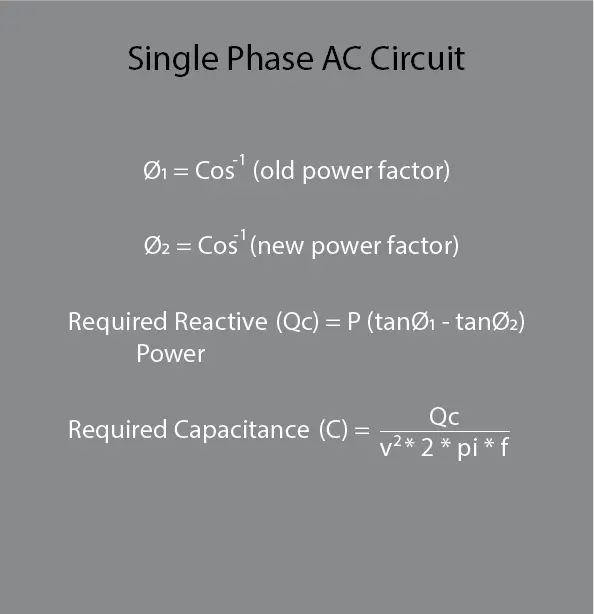
For 1 phase AC circuit:
First we have to convert the given power factors into angle using formula:
From the above formula, we can calculate angle of old and new power factor required.
After angle calculation, the required capacitance reactive power is calculated using the formula:
For the capacitance:
For 3 phase AC circuits:
First we have to convert the given power factors into angle using formula:
From the above formula, we can calculate angle of old and new power factor required.
After angle calculation, the required capacitance reactive power is calculated using the formula:
For the capacitance:
If line to line voltage is given, then first it is converted to phase voltage using formula formula (only valid for Y-connected loads, if delta connected load is given then no conversion is required as in delta connected load phase voltage is equal to line voltage):
Note:
In the above formulas:
- Power factor (p.f) is given in form of unit, ranging from 0 to 1 (for example: 0.8, 0.9). If p.f is expressed in terms of percentage then it is first converted into units by dividing percentage power factor by 100 and then its value is given in the formula.
- If load is Y-connected, and line to line voltage is selected then first convert it in to line to neutral voltage (phase voltage) by 1.73
Solved Example:
For single phase system:
Consider a single-phase AC system that has the following data:
Given:
Voltage (V) =230 V
Power (P) = 1.5 kW
Old power factor (p.f1) =0.7 unit
New power factor (p.f2) =0.9 unit
Frequency (f) =50 Hz
Required:
Required Reactive Power= Qc = ? (KVARs)
Required Capacitance= C = ? (µF)
Solution:
From single phase AC circuit formula
For 3 phase system:
Consider a three-phase system that has the following data:
Given:
Voltage (V) =3815 V (phase voltage)
Power (P) = 20 kW
Old power factor (p.f1) =0.7 unit
New power factor (p.f2) =0.9 unit
Frequency =50 Hz
Required:
Required Reactive Power= Qc = ? (KVARs)
Required Capacitance= C = ? (µF)
Solution:
From 3 phase AC circuit formula
If line voltages are given then we just divide the given line voltage by 1.73 (root 3) (for Y-connection load only if delta connected load is given then no changes required).
For example: for a Y- connected load the line voltage is given as V=6600 V (line to line), while all the other data given remains same:
