Open Phase Condition in Transformers
We are pleased to announce that AllumiaX, LLC. Has now acquired GeneralPAC. This is to add more value through our fundamental courses on Power Systems and provide a platform where students and professionals from all communities can ask and learn in an easy and captivating fashion.
Summary: Amir Norouzi writes about the behavior of three phase transformers when one of the phases is lost. This condition is commonly called a "single phasing". Upon a single phasing condition, Amir describes how voltages and currents (on both the HV side and LV side) greatly depends on the transformer winding connection (delta, wye, wye-grounded etc) as well as the transformer's core construction. Single phasing condition is very difficult to detect by relays where the CTs are monitoring current on the LV side of the transformer. Amir then presents algorithms that identify and detect open phase conditions.
An open phase condition occurs frequent in the power system especially in medium voltage (33kV or below) applications. They also occur in rural or remote areas where the chances of broken conductors, loose connections, and blown fuses are high.
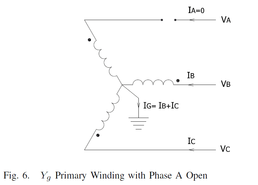
For example, if a 12.5kV to 4.16kV three phase transformer was connected Wye-grounded - Wye-grounded, if only the A phase fuse operated open on the HV side similar to Figure 6 below, this would be considered as a Phase Open or a Single Phasing condition.
This condition is very difficult detect by protective relays. Given the transformer winding connection and transformer connection type, the voltages and currents may be fairly balanced especially in low-loading conditions. In fact, the ground overcurrent or negative-sequence overcurrent protection may not even detect the Open Phase condition due to the symmetry and balance of voltages and currents. This condition may even go unnoticed for a period of time. Open Phase conditions greatly depend on the transformer winding configuration, the transformer core construction, and the transformer loading.
Section II: Three Phase Transformer Construction Types
In Section II-A of the paper, Amir briefly describes the transformer construction types in an effort to provide foresight - that transformer constructions actually make a difference in an Open Phase condition.
The Three-Leg Core Type Transformer is shown in Figure 1 below. This three phase transformer can have a Delta connected primary or a Wye connected primary. Similarly, there are also Four-leg and a Five-leg Core Type transformers construction available by manufacturers. All three construction types provide their own respective advantages. But they also have their own disadvantages.

Advantages of Three-Leg Core Type Transformer
- Makes high voltage insulation easier
- Less Leakage Flux
Disadvantages of Three-Leg Core Type Transformer
- No return path for zero sequence flux.
- Zero sequence flux travels through the air gap or tank which has a much higher magnetic reluctance than the core.
- Due to the high magnetic reluctance of zero sequence flux, the three-leg core type require much higher amount of zero sequence magnetizing current which lead to saturation and excessive heating. This issue is addressed with Four-leg and Five-leg contractions.
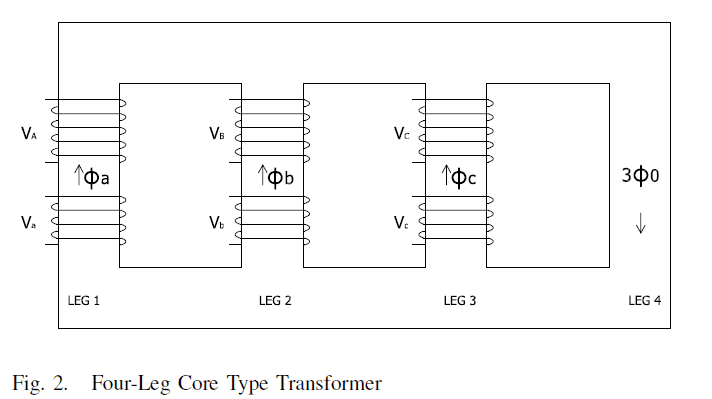
The Four-Leg and Five-Leg Core Type have similar performances compared to Three-Leg Core when it comes to the zero sequence flux. Both types provides a low reluctance path for zero sequence flux (through the core instead). As a result, we get low zero sequence magnetizing current and large magnetizing reactance.
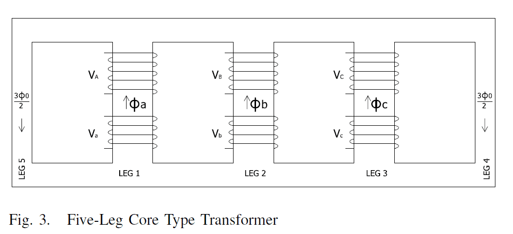
The Five-Leg Core helps reduce the size of the yoke as it will carry less zero sequence flux resulting in a smaller transformer size.
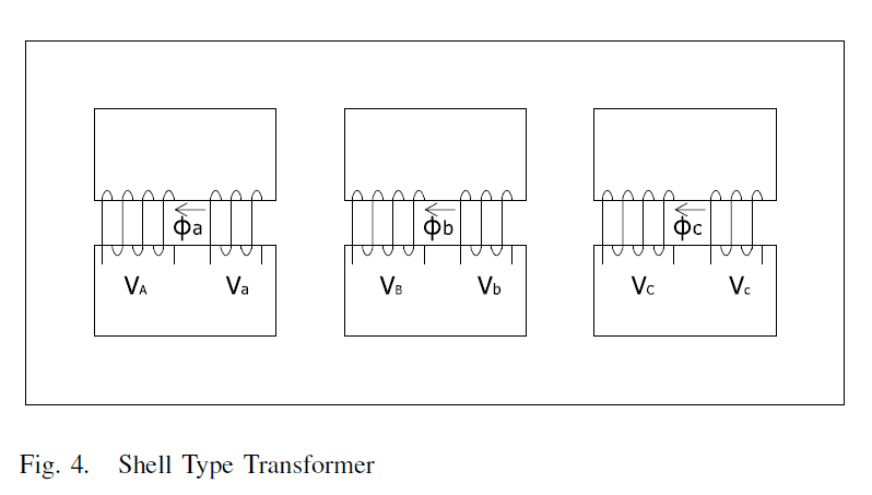
Advantages of a Shell Type Transformer
- Provides a return path for zero sequence flux which means the path has a very small magnetic reluctance (because the flux travels through the core) as opposed to a Three-Leg core type transformer.
- Due to a small magnetic reluctance, it requires smaller amount of zero sequence magnetizing current which lead to less saturation and less heating.
Section III: Analysis of Open Phase Condition
In this section, Amir analyzes voltages and currents for three phase transformers given that one of three phases is open, or in other words, we have an Open Phase or Single Phasing condition. To analyze this condition, the following assumptions must be stated clearly:
- Open phase condition or loss of a phase refers to one phase of three phases being physically and unintentionally disconnected on the primary side of the transformer. This could occur for several reasons such as a loose cable, a broken conductor, a blown fuse, a circuit breaker with one defective contact, etc.
- Primary and high side (and HV) terms are used interchangeably
- Secondary and low side (and LV) terms are used interchangeably
- Open phase is assumed to have occurred on the primary side of a transformer.
- There are no current transformers (CT) or protection voltage transformers (PT) on the high voltage terminals of the transformers being discussed.
Section III-A: HV side investigation
In this section, Amir describes voltages and currents from the HV prospective given an open phase condition with the assumptions described above. Since we are only looking at the HV side of the transformer, the LV winding connection is irrelevant. Or in other words, it doesn't matter if the LV winding connection is a Delta, Wye, or Wye-grounded connection. The analysis in Section III-A is independent of the LV winding.
It is to be noted that a HV Wye-grounded transformer connection has different voltage and current characteristics compared to the HV Wye-ungrounded or a HV Delta connection during an open phase condition. This is a very important distinction to make and keep in mind as we go through the analysis.
Section III-A-1: HV (primary) Wye-grounded connection
If the HV side of the transformer (primary side) was connected Wye-grounded similar to Figure 6 and we had a 3-Leg Core Type transformer connection, the primary winding with the lost phase will have an induced voltage equal to the voltage before the open phase condition.
This basically means that if we look at the voltage alone across the transformer windings before and after the phase was lost, it will be the same. We should expect no difference in voltage on the HV side for a loss of phase given the conditions above. This is counter-intuitive however, it has to do with the summation of fluxes for three-leg core type transformer that Amir eloquently described in Section III-A-1 (page 4).
To summarize this point clearly: we should have expect no discernable difference in voltage across the HV winding for an open-phase condition (as opposed to balanced conditions) given the following scenario
- Utility grid is supplying strong three-phase balanced voltages prior to open-phase condition
- Transformer HV winding connection is Wye-grounded.
- The LV winding connection doesn't matter
- Transformer is a 3-Leg Core Construction Type
- Since the HV winding still develops voltage across the winding even though the phase was lost, the corresponding LV winding will also develop voltage across it, and the LV phase/line currents will be relatively balanced - as if the phase was never lost. From the load's prospective, it sees no difference between Open Phase vs balanced conditions. Remember, this is only for HV transformer connected Wye-grounded and the construction is a 3-Leg Core Type.
For other construction-types such as a 4-leg, 5-leg core type or a shell construction type, (given a Wye-grounded primary) if we have an open phase condition, we will have very little voltage developed across the winding for which the phase was lost. For example, if phase A fuse was blown as shown in Figure 6, we will have very little voltage across winding A on the HV side which results into very little voltage across winding a on the LV side.
To summarize this point clearly: we should expect very little (or even zero) voltage develop across the winding for which the phase was lost given the following scenario
- Utility grid is supplying strong three-phase balanced voltages prior to open-phase condition
- Transformer HV winding connection is Wye-grounded
- The LV winding connection doesn't matter
- Transformer is a 4-Leg Core Type, or 5-Leg Core Type, or Shell Type construction
- Since HV winding will not develop very much voltage across the winding for which the phase was lost, the corresponding LV winding will not develop very much voltage across it. So from the load's prospective, it receives abnormal voltages and currents from two phases but very little (or even zero) from the phase that was lost on the HV side.
Section III-A-2: HV (primary) Wye-ungrounded or Delta Connection
In this section, Amir goes through the same exact scenario but this time, he discusses what would happen to the voltage across the transformer winding if we had an ungrounded primary connection. An ungrounded primary connection means that we have either a delta connection or an ungrounded Wye connection.
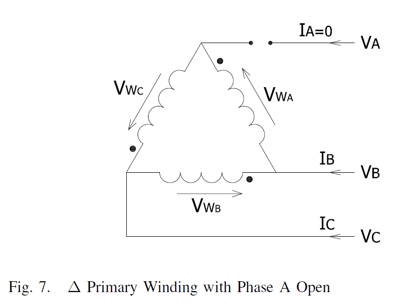
Amir describes Figure 7 as a DAB or a D1 transformer connection. However, this illustration appears to be a DAC or a D11 connection. This is easily verified by looking at the polarity of the transformer winding. Figure 7 clearly indicates that the polarity side of winding A is connected to the non-polarity side of winding C -- suggesting a DAC connection.
For a D11 transformer connection similar to Figure 7, we should expect the voltage developed across winding B to be not affected by the blown fuse on line A. Therefore winding B voltage is healthy and we should expect it to equal VBC.
We should expect the voltage to develop across winding A and winding C to equal one half of VBC voltage. It's half because VBC is the voltage that's measured across winding A and winding C in series. Because they are in series in an open phase condition, it's very similar to a voltage divider type of problem. If we assume the impedance of all three windings are exactly the same, then the voltage developed across both winding A and winding C will be exactly one half of the source voltage. The negative sign comes into play as a result of how we've decided to measure the voltage across winding A and winding C.
So to recap, we will get the following voltage if:
V ωB = V BC
V ωΑ = V ωC =− 1 2 V BC = 1 2 V BC ∠180°
- The fuse in line A operates open and creates an open phase or single phasing condition
- We have a DAC or a D11 transformer connection
- Our system has an ABC phase sequence
- This is irrespective of the transformer construction type. It doesn't matter if we have a 3-Leg, 4-leg, 5-leg Core Type construction transformer. Or if we have a Shell Type construction transformer.
- Since the HV delta connection is an ungrounded-primary, one of the windings will see the full system voltage provided by the utility grid. However, the other two windings will only develop half of the system voltage. Therefore only half of the voltage will be developed across two windings on the LV side. From the loads prospective, they will receive unbalance set of voltages and currents. One winding to be full but the other two will be half.
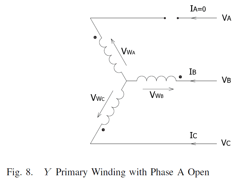
For a HV Wye-ungrounded connection, the process is very similar to the delta connection. However, the following voltages are developed across the Wye-ungrounded windings.
V ωΒ = 1 2 V BC
V ωΒ =− 1 2 V BC
I Line, A =0
I Line, B =− I Line, C
It makes sense to for winding A to be zero because we have a Wye connected transformer. Winding B and Winding C will have one-half of the VBC voltage. Again, the process is very similar to a voltage divider. We get a negative sign in front of winding C because of how we've decided to measure the voltages. And Line current A is equal to zero which makes sense. Line current C is going to equal the magnitude of line current B however, the sign will be opposite. So they both will have same magnitude but will flow in the opposite direction.
A few points to summarize for the HV Wye-ungrounded connection:
- The fuse in line A operates open and creates an open phase or single phasing condition
- We have a Wye-ungrounded connection
- Our system has an ABC phase sequence
- This is irrespective of the transformer construction type. It doesn't matter if we have a 3-Leg, 4-leg, 5-leg Core Type construction transformer. Or if we have a Shell Type construction transformer.
- Since the HV connection is an ungrounded-primary (we have a Wye-ungrounded connection), one of the windings will see the no voltage developed at all. However, the other two will develop only half of the system line-to-line voltage. Therefore only half of the voltage will be developed across two windings on the LV side. And one winding will have no voltage at all. From the loads prospective, they will receive half of the voltages from two windings of the transformer. The currents through those windings will be equal magnitude but in opposite direction. And no voltage and no current from the third winding at all. So the voltages and currents overall will be highly unbalanced.
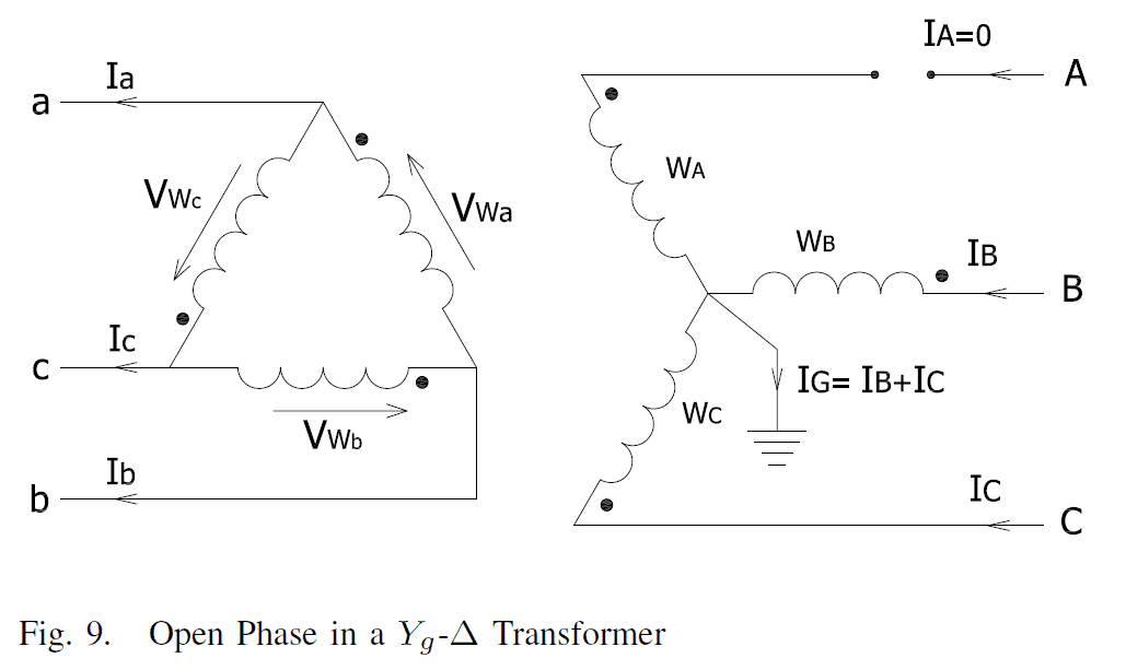
In a very similar manor, Amir goes through the scenario of an open phase condition for a Wye-grounded - Delta transformer connection as shown in Figure 9. As well as a Delta - Wye-grounded transformer connection shown in Figure 14.